


31
RFSDV24/34 Freestanding Direct Vent Gas Fireplace
10003550
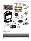
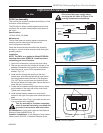
FK24 Fan Assembly
This auxiliary fan system increases the efficiency of the
circulation of the heating air.
The FK24 fan kit allows variable speed control of the
circulation fan and also incorporates a heat sensor in
the circuit.
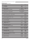
Specifications
115 Volt / 60Hz / 56 Watts
Maintenance
The fan itself does not require regular maintenance,
however periodic cleaning of the fan and the
surrounding area is required.
Check the fan and the area around the fan assembly
and wipe or vacuum at least once per month during the
operating season.
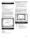
Installation
NOTE: The FK24 is an option for Model RFSDV24;
standard with model RFSDV34. Install fan before
connecting gas line to fireplace.
1. Open front access door; remove the cover valve.
2. Remove pre-mounted fan bracket at the rear of the
pedestal. Remember this location for reinstallation.
3. Open the fan kit; mount FK24 replacement fan
bracket. (Fig. 37)
4. Install the fan through the opening of the front
access door, with the outlet pointed up and the fan
mounting bracket toward the rear of the fireplace.
(Fig. 38) The fan mounts over two studs that hold
the fan just below the firebox floor. Secure the fan in
place with two nuts provided.
5. Locate the fan speed control/junction box on screw
studs located on the right side of the cover valve.
Tighten with nuts provided.
6. Install thermal sensor element on screw studs
located to the right of the gas valve below the burner
base.
7. Reinstall cover valve. Plug in grounded service cord
to a convenient wall receptacle.
This fan assembly is furnished completely
wired. It must be electrically connected and
grounded in accordance with local codes.
US installations: Follow local codes and the National
Electrical Code ANSI/NFPA No. 70.
Canadian installations: In the absence of local codes,
follow current CSA C22.1 Canadian Electrical Code.
Fan Kits
Black
White
Ground
FP394
WIRING DIAGRAM
11/20/96
Fan
Temperature Sensor
Speed Control
FP1025
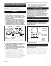
Fig. 35 FK24 fan wiring.
Disconnect the power supply before
servicing the fan. Refer to Figure 35 for
rewiring replacement components.
FP1518
Fig. 36 FK24 fan with existing fan bracket.
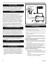
FP1519
Fig. 37 FK24 fan kit with replacement fan bracket.
CFMFP
FK24 Fan install
6/04
Stud
Fan Sensor
Location
Fan Speed
Control/Junc-
tion Box
FP1520
Fig. 38 FK24 fan installation.
Optional Accessories