


17
RFSDV24/34 Freestanding Direct Vent Gas Fireplace
10003550
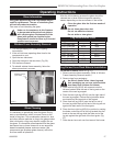
Only glass approved by CFM Corporation may be
used for replacement. The use of substitute glass
will void all product warranties.
Take care to avoid breaking the glass.
Under no circumstances is this fireplace
to be operated without the front glass or
with a broken glass. Replacement of the
glass (with gasket) as supplied by the
manufacturer should be done by a licensed
qualified service person.
1. Turn the gas supply OFF (Refer to Lighting
Instructions).
2. If the unit has been operating allow time for the
components to cool.
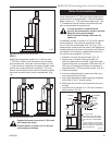
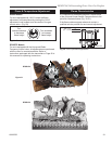
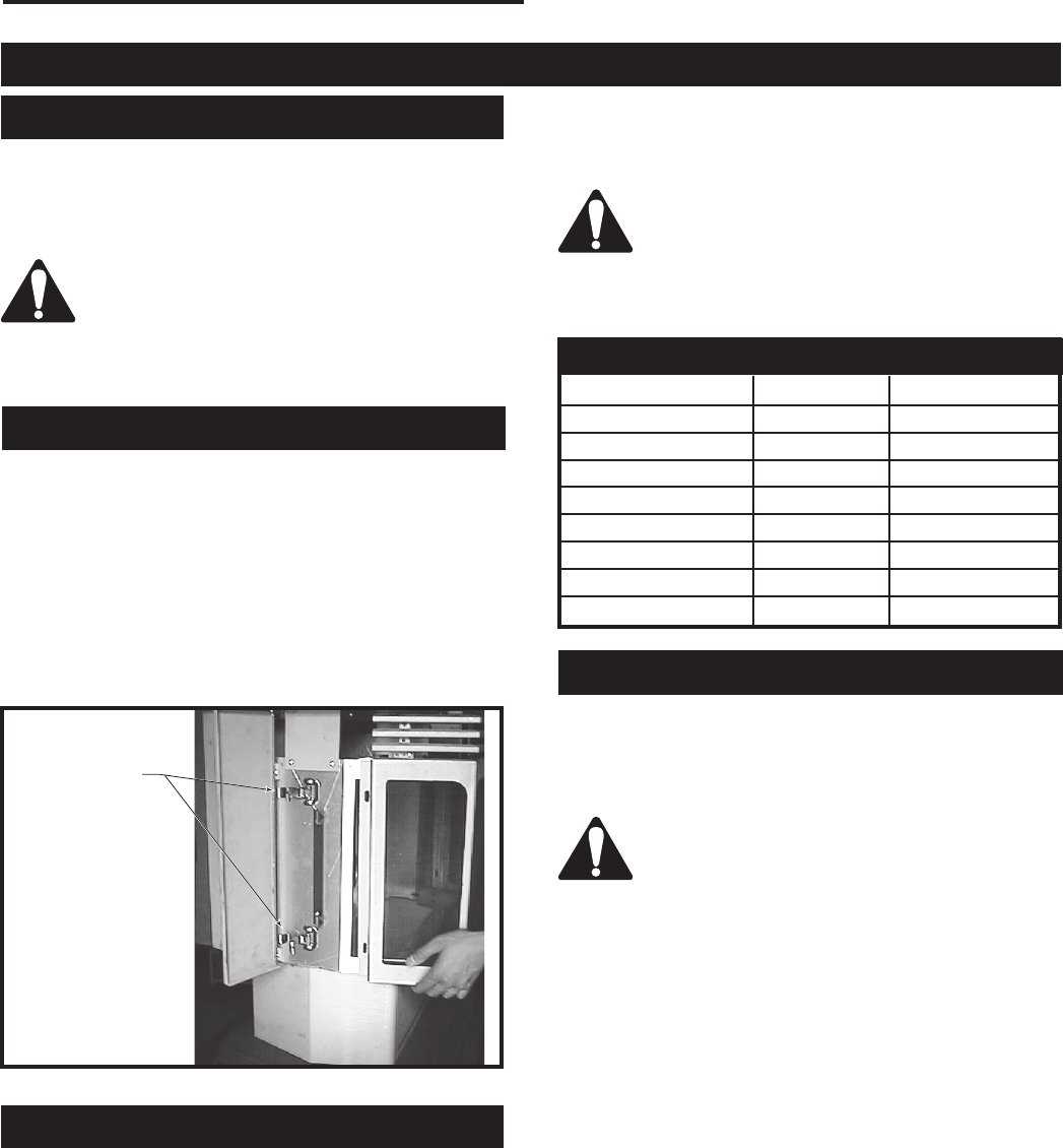
3. Open the two side doors.
4. Open the clamps on the two sides. (Fig. 26)
5. Pull the frame forward.
6. To reinstall window frame assembly, follow the
above procedure in reverse.
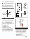
It is necessary to periodically clean the glass. During
start-up condensation, which is normal, forms on the
inside of the glass. This condensation causes lint, dust
and other airborne particles to cling to the glass surface.
Also initial paint curing may deposit a slight film on
the glass. It is therefore recommended that the glass
be cleaned two or three times with a non-ammonia
based household cleaner and warm water (We
recommend gas fireplace glass cleaner) within the
first few weeks of operation.
Clean the glass after the first two weeks of
operation.
Do not clean glass when hot.
Do not use abrasive cleaners.
Do not strike or slam glass.
Operating Instructions
Glass Information
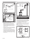
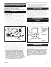
Window Frame Assembly Removal
Glass Cleaning
Release Clamps
(2 per side)
FP1517
Fig. 26 Window frame removal.
After the initial cleaning process the glass should be
cleaned two or three times during each operating
season depending on the environment in the house.
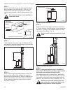
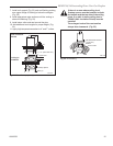
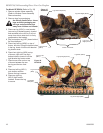
Log Set and Lava Rock Material Installation
For Model RFSDV24 (Refer to Fig. 27)
1. Remove window frame assembly. (Refer to Window
Frame Assembly Removal section)
2. Remove logs from packaging.
As with all plastic items - these logs and
their packaging are not toys and should be
kept away from children and infants.
3. Place rear left log (KR15) with one end onto the
left rear bracket while the rest of the log sets on the
center of the rear log support.
4. Place the rear right log (KR16) onto the right side of
the rear log support. Ensure the log’s bottom holes
are located on the two studs of the support.
5. Place front left log (KR13) onto the left cut out of
the rear log while the front left end of this log will set
against the back wall of the front grate.
6. Place the front right log (KR14) in position by resting
the holes under one end of this log located over the
knob on the rear left log while the other end of the
log set against the right end of the front grate. (Fig.
27)
7. Place burner lava rock over front area of the burner.
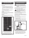
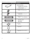
Log Identification Chart
Logs RFSDV24 RFSDV34
Log Ember Bed -- KR7
Log - Front Left KR13 KR8
Log - Front Right KR14 KR9
Log - Rear -- KR10
Log - Top Left -- KR11
Log - Top Right -- KR12
Log - Rear Left KR15 --
Log - Rear Right KR16 --