


10
RFSDV24/34 Freestanding Direct Vent Gas Fireplace
10003550
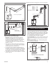
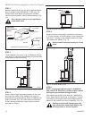
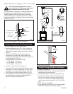
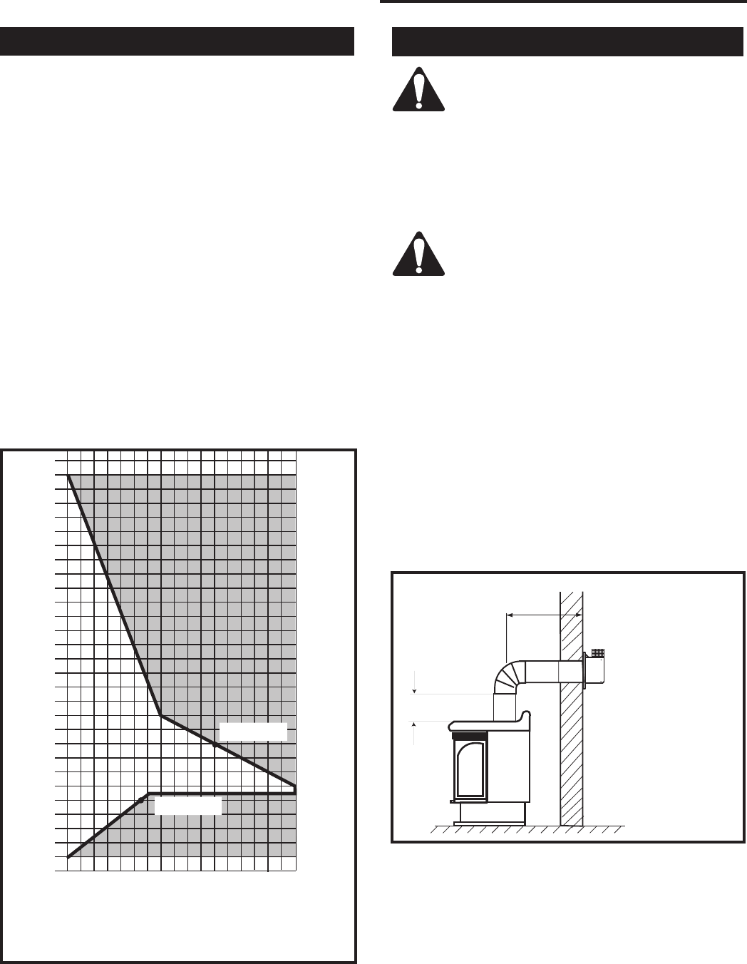
• If a 90° elbow is used in the horizontal vent run
(level height maintained) the maximum horizontal
vent length is reduced by 36” (914 mm). (Fig. 10)
This does not apply if the 90° elbows are used to
increase or redirect a vertical rise. (Fig. 11)
Since it is very important that the vent-
ing system maintain its balance between
the combustion air intake and the flue
gas exhaust, certain limitations as to vent
configurations apply and must be strictly
adhered to.
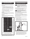
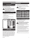
The vent graph showing the relationship between verti-
cal and horizontal side wall venting will help to deter-
mine the various dimensions allowable.
Minimum clearance between vent pipes
and combustible materials is one 1”
(25mm) on top, bottom and sides unless
otherwise noted.
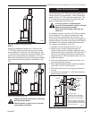
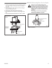
When the vent termination exits through foundations
less than 20” (508 mm) below siding outcrop, the vent
pipe must flush up with the siding.
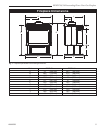
It is always best to locate the fireplace in such a way
that minimizes the number of offsets and horizontal vent
length of vent pipe from the flue collar of the fireplace to
the face of the outer wall.
Horizontal plane means no vertical rise exists on this
portion of the vent assembly.
• The maximum number of 90° elbows per side wall
installations is three (3).
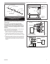
• For RFSDV24 and RFSDV34 models, the maximum
horizontal rn for a minimum 12” (305 mm) vertical
rise is 3’ (914 mm). (Fig. 9)
Vertical Sidewall Applications
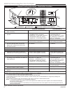
How to Use the Vent Graph
The vent chart should be read in conjunction with the
following vent installation instructions to determine the
relationship of the vertical and horizontal dimensions of
the vent system.
1. Determine the height of the center of the horizon
-
tal vent pipe exiting through the outer wall. Using
this dimension on the Sidewall Vent Graph (Fig. 8),
locate the point intersecting with the slanted graph
line.
2. From the point of this intersection, draw a vertical
line to the bottom of the graph.
3. Select the indicated dimension, and position the
fireplace in accordance with same.
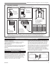
Example A:
If the vertical dimension from the floor of the fireplace is
11’ (3.4m) the horizontal run to the face of the outer wall
must not exceed 14’ (4.3 m).
Example B:
If the vertical dimension from the floor of the unit is 7’
(2.14m), the horizontal run to the face of the outer wall
must not exceed 8¹⁄₂’ (2.6 m).
Horizontal dimension from the outside face of the wall to
the center of the fireplace vent flange
Sidewall vent graph showing the relationship between vertical
and horizontal dimensions for a Direct Vent flue system.
Vertical dimension from the floor of the fireplace to
the center of the horizontal vent pipe
3
4
5
6
7
8
9
10
11
12
13
14
15
16
17
18
19
20
21
22
23
24
25
26
27
28
29
30
3 4 5 6 7 8 9 10 11 12 13 14 15 16 17 18 19 20
Example: A
Example: B
CFM102
DV Graphic
9/28/00 sta
Fig. 8 Sidewall venting graph. (Dimensions in feet)
36”
(914 mm)
x
rev 06-02 rjs
RFSDV24
RFSDV34
x = 12” (305 mm)
FP1495
Fig. 9 Maximum horizontal run.