


14
RFSDV24/34 Freestanding Direct Vent Gas Fireplace
10003550
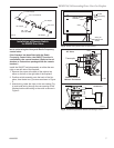
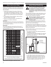
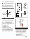
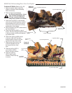
If the foundation is recessed, use recess brackets (not
supplied) for securing lower portion of the snorkel.
Fasten brackets to wall first, then secure to snorkel
with self drilling #8 x 1/2 sheet metal screws. It will be
necessary to extend vent pipes out as far as protruding
wall face. (Fig. 21)
Do not back fill around snorkel. A clear
-
ance of at least 4” (102 mm) must be main-
tained between snorkel and the soil.
BG401
Snorkel
2/10/99 djt
Snorkel
Wall Screws
Foundation Recess
Recess Brackets
Watertight Seal
Around Pipe
Sheet Metal
Screws
BG401
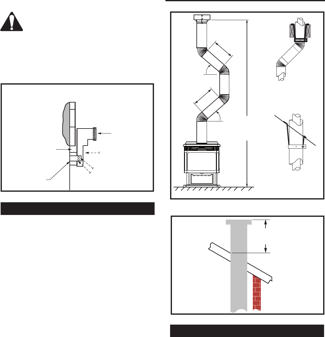
Fig. 21 Snorkel installation, recessed foundation.
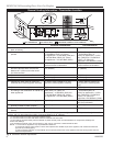
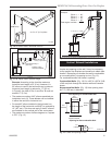
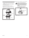
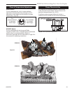
Vertical Through-the-Roof Applications
This Gas Fireplace has been approved for:
• Vertical installations up to 40’ (12 m) in height. Up
to a 10’ (3 m) horizontal vent run can be installed
within the vent system using a maximum of two 90°
elbows.
• Up to two 45° elbows may be used within the
horizontal run. For each 45° elbow used on the
horizontal level the maximum horizontal length must
be reduced by 18” (457 mm).
Example: Maximum horizontal length
0 x 45° elbows = 10’ (3 m)
1 x 45° elbows = 8¹⁄₂’ (2.6 m)
2 x 45° elbows = 7’ (2.1 m)
• A minimum of an 8’ (2.4 m) vertical rise.
• Two sets of 45° elbows offsets within these vertical
installations. From 0 to a maximum of 8’ (2.4 m) of
vent pipe can be used between elbows. (Fig. 22)
• 7DVCS must be used to support offsets. (Fig. 22)
This application will require that you first determine
the roof pitch and use the appropriate starter kit.
(Refer to Venting Components List)
CFM140
Typical vertical through-the-roof application
2/01 sta;
rev. 0602 rjs
Max.
8’
(2.4 m)
45°
Max.
8’
(2.4 m)
45°
Max. 40’
(12 m)
Typical Straight-up Installation
Typical
Ceiling
Support
Application
Typical
Roof Support
Application
CFM140
Fig. 22 Vertical through-the-roof installation.
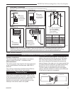
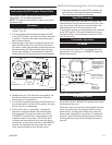
CFM190
TTR Ternim. 2'
1/25/02 sta
rev. 0602 rjs
2’
(610 mm)
Minimum
CFM190
Fig. 23 Proper vent height.
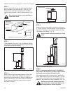
Vertical Through-the-Roof Installation
1. Locate your fireplace.
2. Plumb to center of the 4” (102 mm) flue collar from
ceiling above and mark position.
3. Cut opening equal to 9
³⁄₈” x 9³⁄₈” (240 x 240 mm).
4.
Proceed to plumb for additional openings through
the roof. In all cases, the opening must provide a
minimum of 1” (25 mm) clearance to the vent pipe,
i.e., the hole must be at least 9³⁄₈” x 9³⁄₈” (240 x 240
mm).
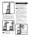
5. Place fireplace into position.
6. Place firestop(s) #7DVFS or Attic Insulation Shield
#7DVAIS into position and secure. (Fig. 24)