


8
NV360/580 Series
20003565
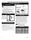
Install the Venting System,
Flashing and Termination
NOTE: The NV360 uses a 6" B-vent system. The
NV580 uses an 8" B-vent system (refer to Accessories,
Page 23 for adapter).
Refer venting installation instructions provided by the
B-Vent manufacturer.
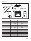
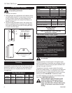
Refer to Page 4, Figure 1 to locate chimney centerline
dimension from a combustible back wall.
•
Minimum vertical chimney height — 12 feet (3.65 m).
(measured from the bottom of the fireplace)
• Maximum vertical height — 40 feet (12 m).
• Minimum height with two (2) elbows — 18 feet (5
m)
• Elbow requirements allow a maximum of two (2)
90° elbows or four (4) 45° elbows per installation.
(Two (2) 45° elbows = One (1) 90° elbow.) Refer to
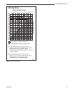
the venting chart for proper elbow offset runs.
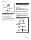
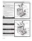
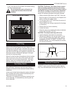
For firestop positioning, refer to Figure 8. Only one (1)
firestop required per frame. NOTE: A firestop is not
required at the roof.
Fig. 8 Firestop/draftstop positions.
FP384
FIRESTOP
11/21/96
adapted from IGF53
FP384
Attic Installation
Firestop position when area above ceiling is an attic.
Nail (4)
Firestop Spacer
Joist
Ceiling Installation
Firestop position when area above ceiling is NOT an attic.
(Firestop/draftstop ap-
pearances my vary. Only
1 firestop required per
frame.)
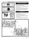
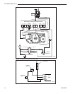
FP580
INSTA VENT FREE
EB1 JUNCTION BOX
11/18/97
OUTSIDE
FRONT OF UNIT
INSIDE
FRONT OF UNIT
Electrical Box
FP580
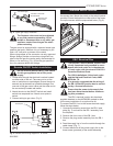
Fig. 7 EB-1 receptacle.
6. Connect the white wire of the power line to the
chrome screw of the socket assembly.
7. Connect the ground wire of the supply line to the
green screw of the socket assembly.
8. Refit the socket assembly back into the electrical
box and replace the cover plate. Secure the cable
with the clamp on the outside of the unit to prevent
strain on the connections.
9. The EB-1 electrical junction box is now ready to sup-
ply power to the FK12 or FK24 fan kits if fitted.