


25
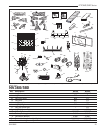
NV360/580 Series
20003565
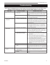
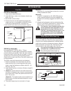
Remote Controls
Optional remote control units are available to control
different functions of the appliance.
Model Functions Controlled
RC1 ON/OFF
RC2 ON/OFF and Temperature
MRC3 ON/OFF and Temperature control with
a digital display and a programmable
24 hour clock
IMT Wall mounted thermostat control
Ceramic Refractory Lining
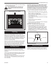
1. Remove glass and logs.
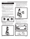
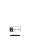
2. Insert supports under ceramic hearth panels. (Fig.
35)
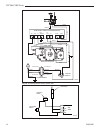
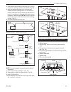
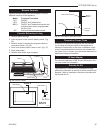
3. Remove three (3) screws securing heat shield to
combustion dome. (Fig. 36)
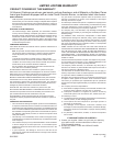
4. Place rear ceramic panel in back of unit. (Fig. 37)
5. Place side panels.
6. Replace heat shield, logs and glass.
H103
heat shield
3/1/99 djt
Heat Shield
Section A
Heat Shield
(3)
Screws
H103
Fig. 36 Heat shield.
H102
rear ceramic support
2/23/99 djt
Rear Ceramic Panel
Back of
Firebox
Burner
Rear Log
Support
H102
Fig. 37 Rear ceramic panel placement.
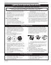
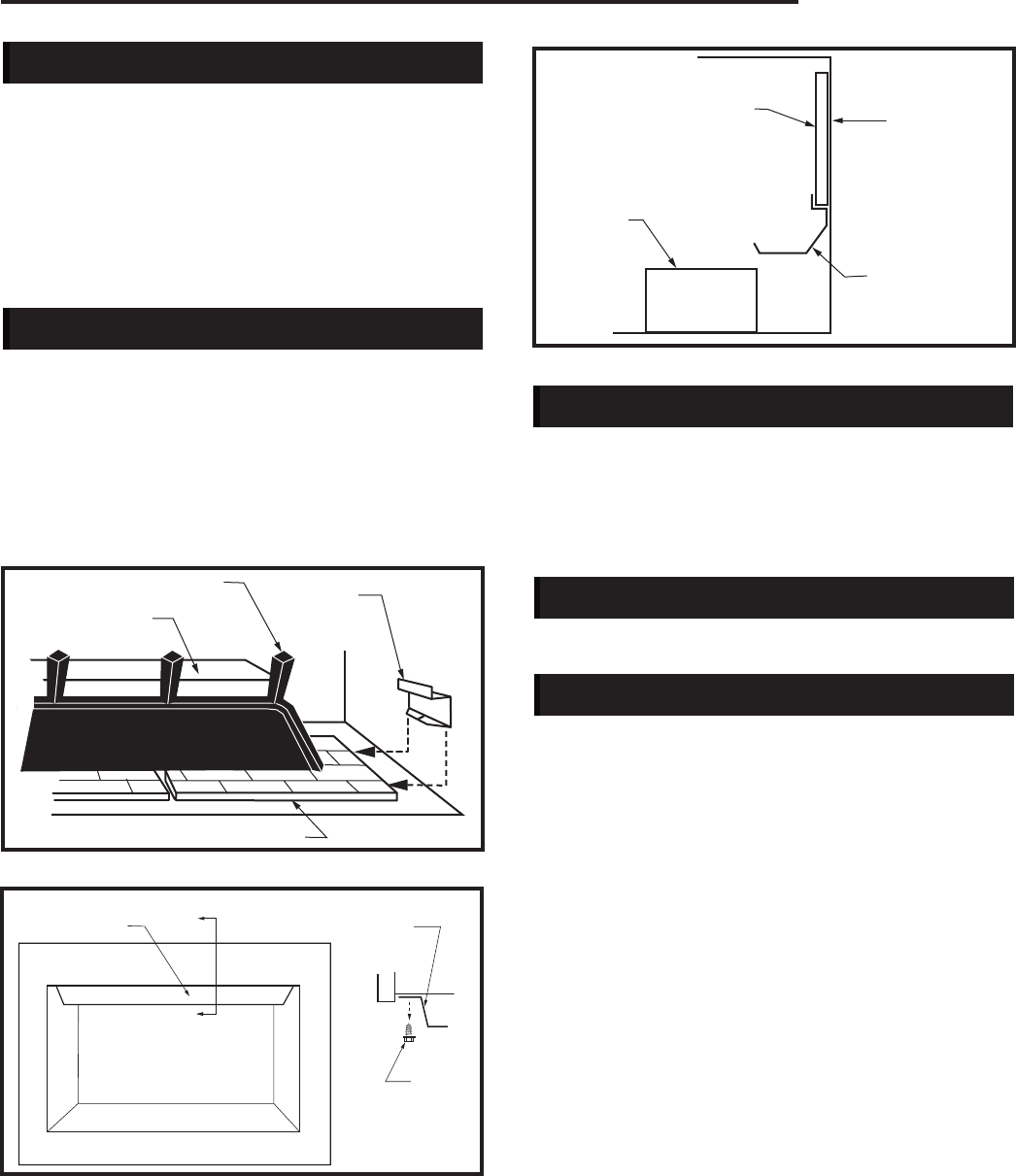
Decorative Frame Trims
A selection of decorative frame trim kits are available
for moutning around the outside of the appliance to
enhance its visual effct on the room. Installation instru-
citons for each decorative frame trim are included with
the frame trim kit. Contact your authorized distributor for
details and ordering information.
B-Vent Adapter
For use with other than VCMP B-vent (SK-8) pipe. Con-
tact your dealer for information.
Outside Air Kit
The model AK-1 Outside Air Kit is designed to bring
additional combustion air directly from the outside to the
fireplace. Refer to installation instructions provided with
the Outside Air Kit.
Side View
Section A
H101
Ceramic Panel Supports
3/16/99 djt
Burner
Grate
Ceramic
Support
H101a
Hearth Panel
Fig. 35 Ceramic support.