


12
NV360/580 Series
20003565
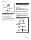
Inspecting the Venting System
This appliance venting system was designed and con-
structed to develop a positive flow adequate to remove
flue gases to the outside atmosphere.
Any foreign object in the venting system, except those
designed specifically for the venting system, may cause
spillage of flue gases.
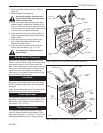
To inspect the venting system, make sure the main gas
valve is off. Remove glass frame (See Window Frame
Assembly Removal Section). Using a flashlight, check
the area above the baffle in the combustion dome.
Clean if necessary.
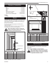
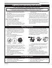
Test Chimney Draw
A "Chimney Draw" test must be made before the instal-
lation is complete.
1. Close all doors and windows in the home and start
exhaust fans in the kitchen and bathroom.
2. Light unit and operate for 5 minutes.
3. Hold an ignited match, cigarette or smoke match in
front of the unit. Refer to Figure 17 for location of the
draft hood opening.
4. Check to make sure smoke from the match, ciga-
rette or smoke match is drawn into the fireplace. If it
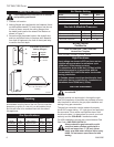
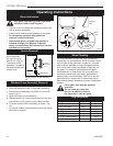
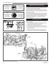
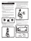
LO
HI
Turn
counterclockwise
to increase
flame height
Turn clockwise
to decrease
flame height
HV102
Honeywell hi/lo knob
4/5/99 djt
HV102
Fig. 13 Flame adjustment knob for Honeywell valve.
Turn
counterclockwise
to increase
flame height
Turn clockwise
to decrease
flame height
HV116
SIT 820 knob
1/14/02 djt
I
H
LO
HV116
Fig. 14 Flame adjustment knob for SIT 820 valve.
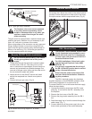
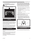
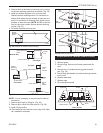
F584-703
Honeywell
& PSE
pilot flames
3/8" - 1/2"
(10 - 13 mm)
SIT Pilot
PSE Pilot
F584-703
Fig. 15 Correct pilot flame appearance.
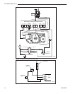
LG118
DV360
logs
1/26/00 djt
LG121
DV580
log flames
1/27/00 djt
Yellow Flame
Yellow
Flame
Red Glow
Red Glow
LG121
LG118
DV360
DV580
Fig. 16 Correct burner flame appearance.