


6
NV360/580 Series
20003565
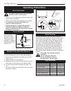
Gas Line Installation
When purging gas line the front glass must
be removed.
The gas pipeline can be brought in through the right
side of the appliance. Knockouts are provided at conve-
nient locations to allow for the gas pipe installation and
testing of any gas connection.
The gas line connection can be made with properly
tinned 3/8” copper tubing, 1/2” rigid pipe or an approved
flex connector. Since some municipalities have addi-
tional local codes, it is always best to consult your local
authority and the CSA-B149.1 installation codes.
For USA installations consult the current National Fuel
Gas Code, ANSI Z223.1/NFPA 54.
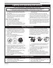
Always check for gas leaks with a mild
soap and water solution applied with a
brush no larger than 1” (25 mm). Never
apply soap and water solution with a spray
bottle. Do not use an open flame for leak
testing.
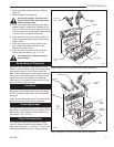
Framing and Finishing
Check appliance to make sure it is levelled
and properly positioned.
1. Choose unit location.
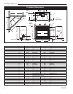
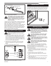
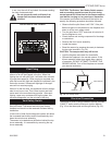
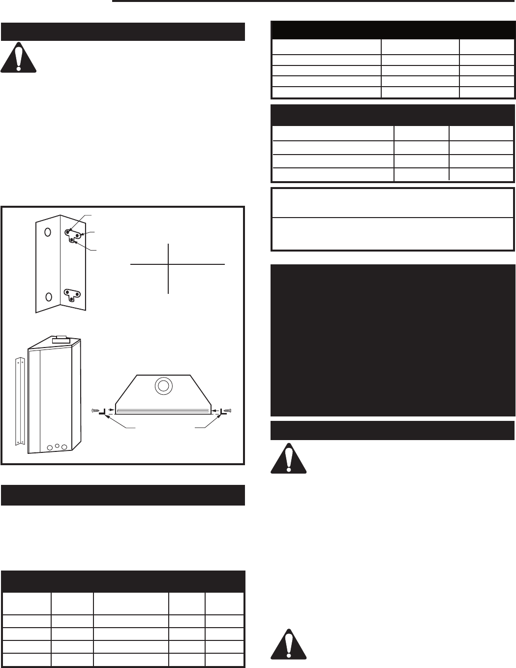
2. Nailing flanges are supplied with the fireplace (found
on the fireplace hearth). To level the box and secure
it firmly in place, remove the nailing flanges from
the hearth and install at the sides of the firebox as
shown in Figure 3.
3. Screw through the slotted holes in the drywall strip
and into pre-drilled holes in fireplace side. Measure
from face of fireplace to the face of the drywall strip
to confirm the final depth.
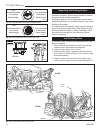
Finishing
Noncombustible materials such as brick and tile can
be extended over the face of the unit (Do not cover the
glass door or grille). If a trim kit is to be installed, brick
and tile will have to be installed flush with the side of
this appliance.
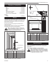
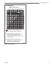
Gas Specifications
Max. Min.
Model Fuel Gas Control Input Input
NV360RN Natural Millivolt Hi/Lo 33,500 23,500
NV360RP Propane Millivolt Hi/Lo 33,500 23,700
NV580RN Natural Millivolt Hi/Lo 45,000 31,500
NV580RP Propane Millivolt Hi/Lo 45,000 31,900
NV360 / NV580
Certified to
ANSI Z21.50b-2002 / CSA 2.22b-2002
Vented Gas Fireplace
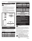
High Elevations
Input ratings are shown in BTU per hour and are
certified without deration for elevations up to
4,500 feet (1,370m) above sea level.
For elevations above 4,500 feet (1,370m) in USA,
installations must be in accordance with the
current ANSI Z223.1/NFPA 54 and/or local codes
having jurisdiction.
In Canada, please consult provincial and/or local
authorities having jurisdiction for installations at
elevations above 4,500 feet (1,370m).
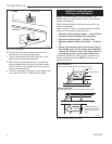
Minimum Inlet Pressure 5.5" w.c. 11" w.c.
Maximum Inlet Pressure 14.0" w.c. 14.0" w.c.
Manifold Pressure 3.5" w.c. 11" w.c.
Natural
LP
Gas Inlet & Manifold Pressures
Units: H31A00, H31B00, I31A00, I31B00
FP1023
side nailing flange
1/27/00 djt
C
A
B
Adjustable Drywall Strip
(Nailing Flanges)
Screw Drywall
Position Depths
A 1/2" / 13 mm
B 5/8" / 16 mm
C 3/4" / 19 mm
Adjustable
1/2", 5/8" & 3/4"
Spacing
FP1023
Fig. 3 Nailing flanges.
Air Shutter Setting
Model Front Rear
NV360RN closed closed
NV360RP open open
NV580RN closed closed
NV580RP open open