


18
NV360/580 Series
20003565
Fuel Conversion Instructions
To convert the DV360/580 units for use with a different
gas follow these instructions. Before proceeding, turn
control knob on valve to “OFF” and turn gas supply
OFF. Turn OFF any electricity that may be going to the
appliance.
CAUTION: Logs may be HOT! Allow to cool before
proceeding.
1. Open louvre assembly bottom to gain access to
valve. Remove window frame assembly. (See “Win-
dow Frame Assembly Removal”, Page 10, Fig. 10)
2. Remove logs if previously installed.
Honeywell Valve
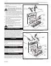
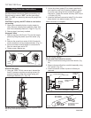
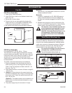
1. Remove cap from HI/LO knob. This can be accom-
plished by lifting the plastic cap off the screw. (Fig.
21)
2. Remove the screw from center of HI/LO knob with
small screwdriver turning counterclockwise. (Fig. 21)
3. Insert conversion screw supplied in conversion kit.
Blue for natural gas, red for LP.
4. Tighten screw, replace cap.
CO100
Gas conversion
HI-LO knob
3/15/99 djt
L
O
H
I
L
O
H
I
Cap
Hi/Lo
Knob
Lift Open
Remove
Center Screw
CO100
Fig. 21 Remove center screw from Hi/Lo knob.
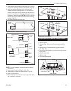
NOVA SIT820 Valve
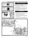
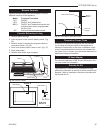
1. Using the TORX T20 bit, remove and discard the
three (3) pressure regulator mounting screws (A),
pressure regulator tower (B) and the spring and
diaphragm assembly (C). (Fig. 22)
FC107
SIT820
valve conversion
10/03
A
B
C
O
F
F
P
I
L
O
T
O
N
FC107
Fig. 22 Remove mounting screws, pressure regulator tower
and spring and diaphragm assembly.
2. Insure the rubber gasket (D) is properly positioned
and install the new HI/LO pressure regulator assem-
bly to the valve using the new screws (E) supplied
with the kit. Tighten the screws securely. (Ref. torque
= 25 in/lb) (Fig. 23)
3. Install the enclosed conversion label (F) to the valve
body where it can easily be seen. (Fig. 23)
Valve conversion is complete.
D
E
F
FC108
SIT
regulator
conversion
10/03
O
F
F
P
I
L
O
T
O
N
FC108
Fig. 23 Replace regulator.
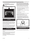
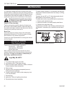
Burner and Pilot Orifice Conversion
1. Remove manifold mounting screw from burner. (Fig.
24)
2. Remove burner orifice from manifold assembly using
3/8” wrench. (Fig. 25)
3. Install conversion orifices in place of orifices just
removed.
CO101a
DV360/580
Gas Conversion
Manifold
1/28/00
added manifold screw
4/7/00 djt
Manifold Assembly
Burner Pan
NV580 Pilot
Location
Manifold
Mounting
Screw
Log Support
Orifice
NV360 Pilot
Location
CO101a
Fig. 24 Remove manifold assembly.
CO102a
DV360/580
Gas Conversion
1/28/00 djt
Rear Burner Orifice
#53 (NV360)
#51 (NV580)
Front Burner Orifice:
#74 (NV360)
#65 (NV580)
CO102a
Fig. 25 Remove burner orifice, replace with new orifice.