


5
NV360/580 Series
20003565
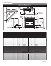
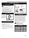
Clearance to Combustibles
Appliances
Top .......................................................... 0” (0 mm)
Bottom ..................................................... 0” (0 mm)
Side ......................................................... 0” (0 mm)
Back ........................................................ 0” (0 mm)
Perpendicular Sidewall ........................... 0” (0 mm)
Top of unit to ceiling .......................... 36” (914 mm)
Front of unit to combustibles ............. 36” (914 mm)
Venting
B-Vent ...................................................
1” (25 mm)
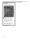
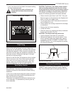
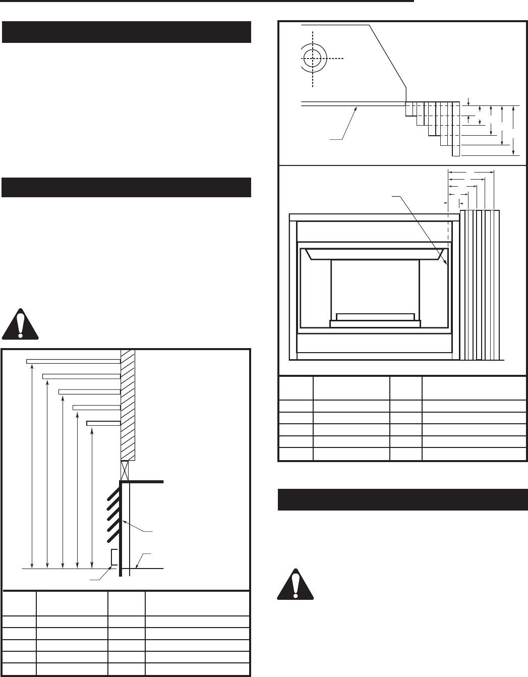
Mantels
The height that a combustible mantel is fitted above the
fireplace is dependent on the depth of the mantel. This
also applies to the distance between the mantel leg (if
fitted) and the fireplace.
For the correct mounting height and widths refer to
Figures 2a and 2b.
Noncombustible mantels and legs may be installed at
any height and width around the appliance.
When using paint or lacquer to finish the
mantel, such paint or lacquer must be heat
resistant to prevent discoloration.
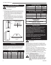
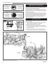
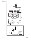
Ref. Mantel Ref. Mantel Leg From
Leg Depth of Comb. Opening
F 14" (356 mm) K 14" (356 mm)
G 12" (305 mm) L 12" (305 mm)
H 10" (254 mm) M 10" (254 mm)
I 8" (203 mm) N 8" (203 mm)
J 1
¹⁄₂" (38 mm) O 1¹⁄₂" (38 mm)
Fig. 2b Combustible mantel leg minimum installation.
CFM170
DV Builder Front
View
O
N
M
L
K
J
F
G
H
I
Mantel
Leg
CFM164a
Mantel Leg Chart
06/22/01 sta
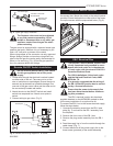
Black
Surround
Face
Side of
Combustion Chamber
CFM170
CFM164
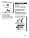
Hearth Extension
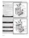
A hearth extension in front of appliance is recommend-
ed but not required. We recommend a noncombus-
tible hearth.
Cold climate installation recommendation:
When installing this unit against a noninsu-
lated exterior wall or chase, it is mandatory
that the outer walls be insulated to conform
to applicable insulation codes.
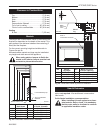
Ref. Mantel Ref. Mantel From Top
Shelf Depth of Comb. Chamber
V 10" (254 mm) A 19" (483 mm)
W 8" (203 mm) B 17" (432 mm)
X 6" (152 mm) C 15" (381 mm)
Y 4" (102 mm) D 13" (330 mm)
Z 2" (51 mm) E 11" (279 mm)
Top of Combustion
Chamber
CFM146
Fig. 2a Combustible mantel minimum installation.
A B C D E
V
W
X
Y
Z
Fireplace
CFM146
DV Mantel Chart
7/5/01 sta
Louvre Assembly Top
Bottom of Door Trim