


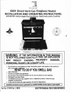
I
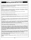
NSTALLATION
I
NSTRUCTIONS
The
appliance;
when installed
must be electrically
connected
and
grounded
in accordance
with
local
codes
or,
in the
absence
of
local
codes,
with the
current
CSA
C22-1
Canadian
Electrical
Code
(Canada)
or the
National
Electrical
Code
ANSIlNFPA 7o-latest
edition
(USA)'
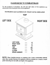
Keep
appliance
area
clear and free
from combustible
materials,
gasoline,
and other
flammable
liquids and
vapours.
lnstallation
and
provision
for combustion
dnd
ventitation
air
must
conform
with
local codes
or,
in absence
of
local
codes,
with
the National
Fuel
Gas
code,
ANSI
2223.1
-
latesl
edition
-
in the
united states
or,
in canada,
with
the
cu?rent
CAN/CGA
-
8149
-
1 or
2Installation
Code'
Turn
gas
supply
on and
check for leaks.
DO
NOT
USE
OPEN
FLAME
Use
soap
and
water solution'
Oo
not
use
this
appliance
if
any
part
has
been
under
water'
lmmediately
call
a
qualified
service
technician
to
inspect
the
room appliance
and to
replace
any
parf
of the
control
systern
and
any
gas
control
which
has
been
under
water'
lhe
appliance
afid
its
individual shutofl
valve
rnust
be
discorrnected
irom
the
r;as supply
piping systern
fourtng
any
pressure testing
of
the
gas
supply
piping system
at
test
pressures
in excess
ol
1'2
p's'i'g'
(3'5
KPa).
The
appliance
must be
isolated from the
gas
supply
piping
system
by
closing
its
individual
manual
shut off
valve during
any
pressure
testing of.the
gi"
suppiy-piping
system
at
test
pressures
equal
to or
less
than
1/2
p.s.i.g.
(3.5
KPa).
Gas
piping
must
be
installed in accordance
with
local
codes,
or
with
the
latest
edition
of
the
National
Gas
code
ANSI
2223.1
(U.S.A.).
(ln
Canada
-
cANlcGA-B149-1
or
2.) During
pressure testing
of
the
gas
piping
system
supply
the
heater disconnect
or
isolate
the
heater
from
the
piping
system.
The
pressure used
to test
piping sysiems
will damage
the controls
used
on
this
heater..Do
not
use
flexible
hose.
Unions
in
gas
tines should
be of the
ground
joint
type.
Compounds
used
on
threaded
ioints
of
gas
piping
must
be
resistant
to the action
of liquefied
petroleum
gas'
Gas
piping
must
be ol sufficient size
to
provide
a
minimum
natural
gas
pressure
at
the
appliance
of
4'5
inches
water
column
lor natural
gas
or
11
inches
for
Propane/LP
gases for the
purpose
of
input
adjustment'
The
maximum
inlet
gas pressure
to the
heater
must
not
exceed
10.5
inches
for
nalural
gas
and
13
inches
for
propane/Lp
qases.
lf this
heater is
to
be
supplied
with
LP
gas
(bottled
propane) the tank
or
bottle
supplying
ili;;rrirtir*
a regulator
which
reduces
the
gas
pressure
to between
11 and
13 inches
water
column'
The
controt
will not operate
with
gas
line
pressuie
d'irectly
from the
tank
and
may
leak
gas
due
to
this
excessive
Pressure.
lnclude
a
manual
shut-otf
device and
union
in
the
line
so
the control
or
heater
may
be
disconnected
for
servicing.
Include
a
drip leg and a
plugged
1/8
inch
NPT
tapping
in
the line'
The
tapping
must
be
accessible
for
test
gauge
connection
immediately
upstream
of
the
gas
supply
connection
to the appliance'
Use
a
soap/water
solution or
a liquid
gas leak
detector
to
coat
each
ioint
in the
piping
system,
and
look
lor
bubbles
which
indicates
gas
leaks.
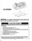
tmportant:
Alt
references
to siliconing
should
be
adhered
to.
Always
use 600'F
(316'c)
high
temperature
silicone.
5