


HOR
IZONTAL
I N STALLATIO
N
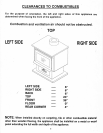
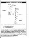
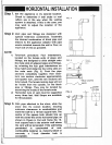
Step
1. Set the
appliance
in it's desired
location.
Check
to
determine
if
wall studs
or
roof
rafters
are
in
the way when
the
venting
system is
attached.
lf this
is the
case,
you
may want
to adjust
the
location
of'
,
the
appliance.
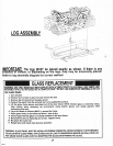
Step
2. Vent
pipe
and
fittings are
designed
with
special
twist-lock
connections.
Assemble
the
desired
combination of
black
pipe
and
elbows
to the
appliance
adaptor
with
pipe
seams oriented
towards the
wall
or floor,
as
much
out
of view
as
possible.
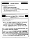
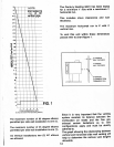
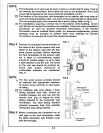
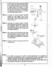
NOTE:
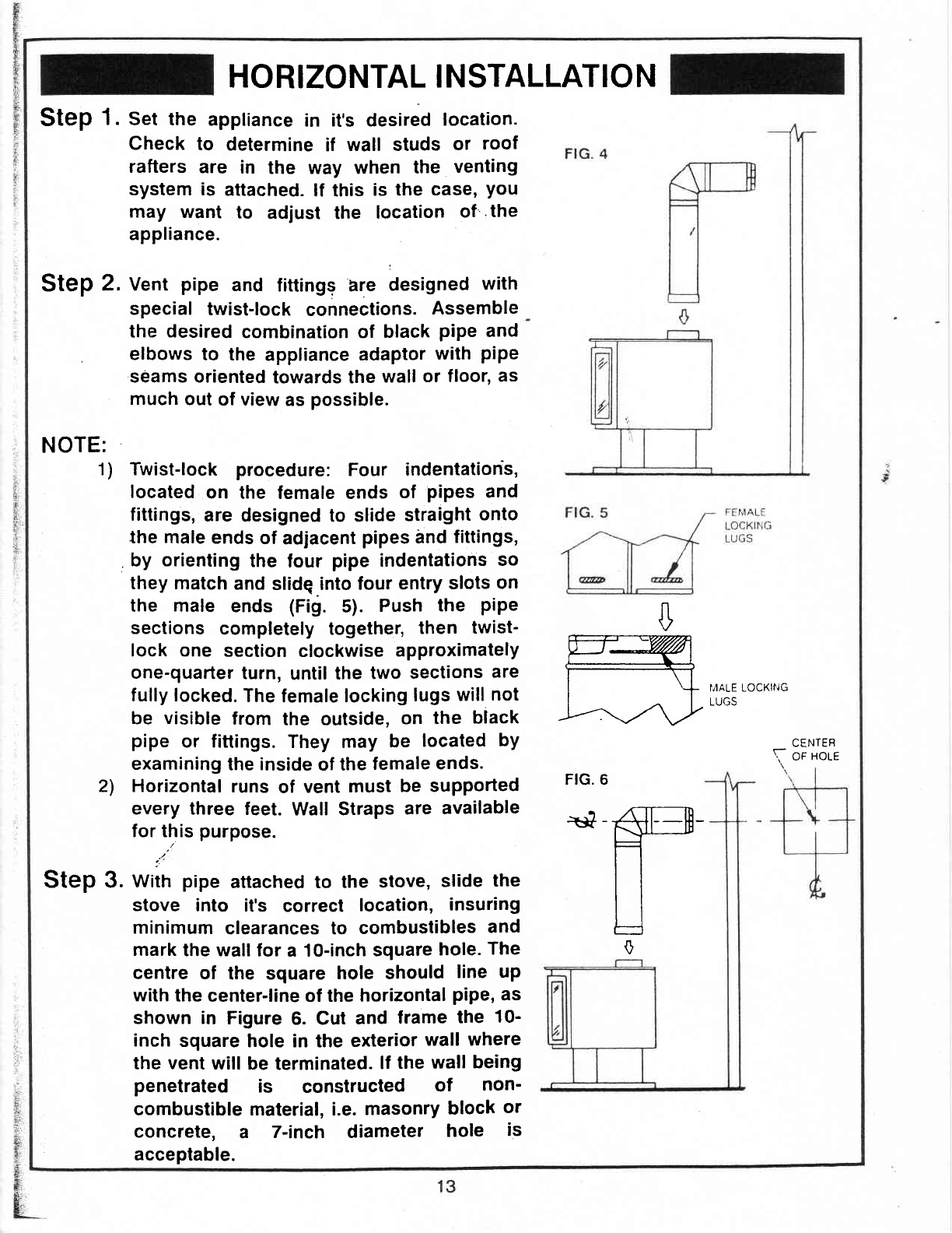
1) Twist-lock procedure:
Four
indentatioris,
located
on
the female ends
of
pipes
and
fittings,
are designed
to slide
straight
onto
the male
ends
of
adjacent
pipes
and
fittings,
.
by
orienting
the
four
pipe
indentatiohs
so
they
match
and
slidg.inlo
four
entry
slots
on
the male
ends
(Fig.
5).
Push
the
pipe
sections
completely together,
then
twist-
lock one
section
clockwise
approximately
one-quarter
turn,
until
the
two
sections
are
fully
locked.
The
female locking
lugs
will
not
be
visible
from
the outside,
on the
black
pipe
or fittings.
They may
be
located
by
examining
the
inside
of the
female
ends.
2l Horizontal
runs
of
vent
must
be supported
every three
feet.
Wall Straps
are
available
for this
purpose.
/
/
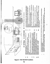
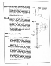
Step
3.
witn
pipe
attached to the
stove,
slide
the
stove
into it's
correct
location,
insuring
minimum
clearances to
combustibles
and
mark
the wall for
a 10-inch
square
hole.
The
centre of
the square
hole should
line up
with
the
center-line
of
the
horizontal
pipe,
as
shown in
Figure
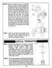
6. Cut
and
frame
the
10-
inch
square
hole in the
exterior
wall where
the
vent
will
be terminated.
lf
the wall
being
penetrated
is
constructed
of
non-
combustible material,
i.e.
masonry
block
or
concrete,
a
7-inch diameter
hole
is
acceptable.
I,,IALE LOCKII'JG
LUUJ
$
ry
[-l
l--':t
rz\.y
FIG. 6
+*ffi
n
|l
tJ
0
CENIEB
OF
HOLE
\-