


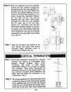
Step
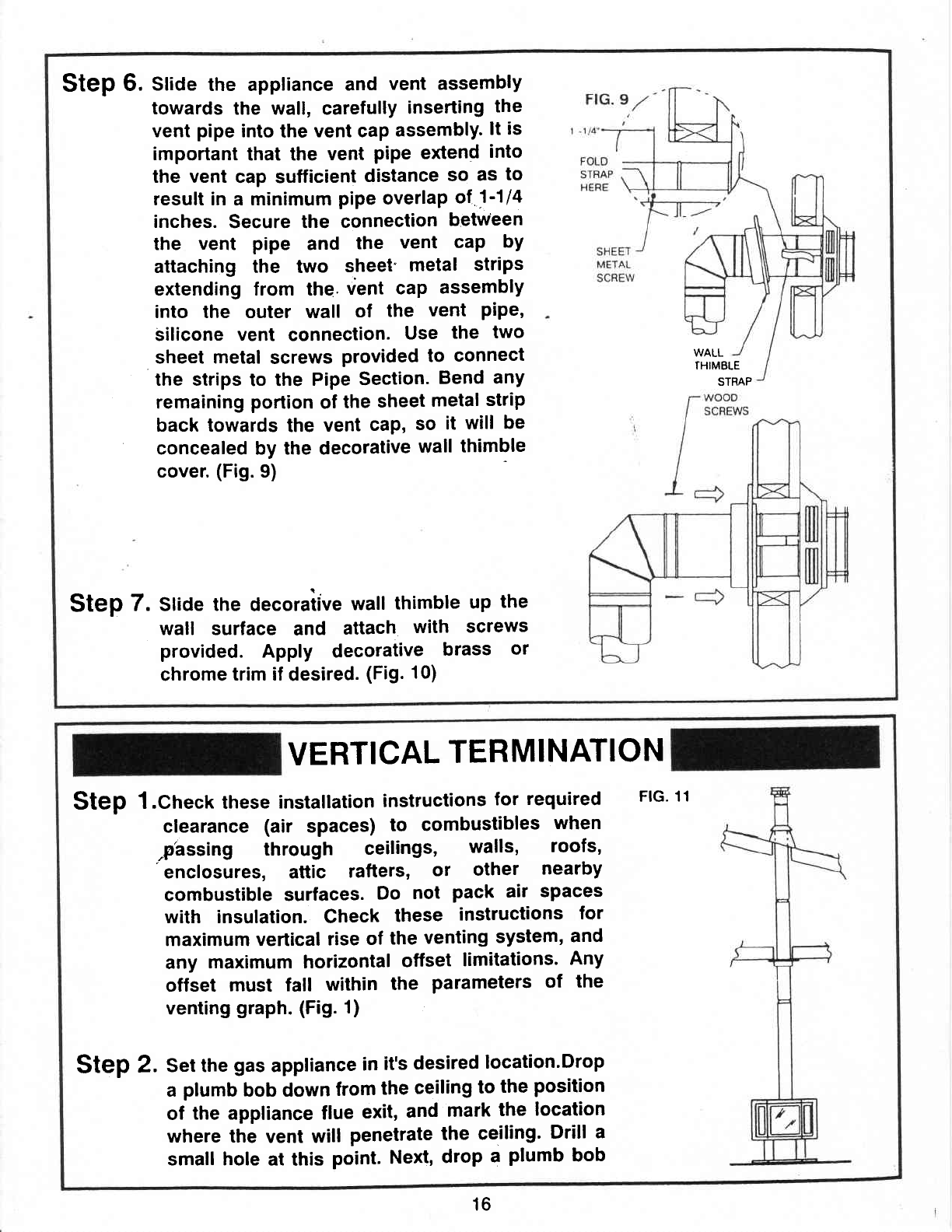
6.
stioe
the appliance
and
vent assembly
towards
the wall, carefully
inserting
the
vent
pipe
into
the
vent cap
assembly.
lt is
important
that the
vent
pipe
extend
into
the vent
cap sutficient
distance
so
as
to
result in
a
minimum
pipe
overlap
ol
1'1la
inches.
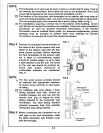
Secure the
connection
between
the
vent
pipe
and
the
vent
caP
bY
attaching the two
slreet"
metal
strips
extending from the.
vent
cap
assembly
into the outer wall
of
the
vent
PiPe,
silicone
vent
connection.
Use
the
two
sheet metal
screws
provided
to
connect
the strips
to the
Pipe
Section.
Bend
any
remaining
portion
of
the
sheet
metal
strip
back towards
the
vent
cap,
so
it
will
be
concealed by the decorative
wall
thimble
cover.
(Fig.9)
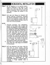
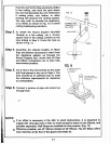
Step
7. Stioe
the
decorative
wall
thimble
up
the
wall surface
and
attach
with
screws
provided.
Apply decorative
brass
or
chrome
trim if
desired.
(Fig.
10)
WALL
THIMBLE
STRAP
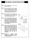
VERTICAL
TERMINATION
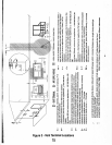
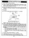
Step
l.Chect these
installation
instructions
for
required
FlG.
11
clearance
(air
spaces)
to
combustibles
when
phssing through
ceilings,
walls,
roofs,
'enclosures,
attic
rafters,
or
other
nearby
combustible surfaces.
Do
not
pack air
spaces
with insulation. Check
these
instructions
for
maximum vertical
rise
of
the
venting
system,
and
any
maximum horizontal
otfset
limitations'
Any
offset
must falt
within
the
parameters
of
the
venting
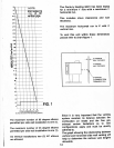
graph.
(Fig. 1)
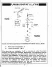
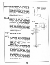
Step
2.
Set the
gas
appliance
in
it's
desired
location.Drop
a
plumb
bob down
from
the
ceiling
to
the
position
of
the appliance flue
exit,
and
mark
the
location
where the
vent will
penetrate
the
ceiling'
Drill
a
small hole
at this
point.
Next,
drop
a
plumb
bob
16