


;i
ii
i,..
'in
i5
*.::
F
ts
*i
&.
F
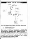
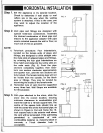
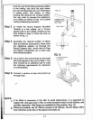
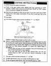
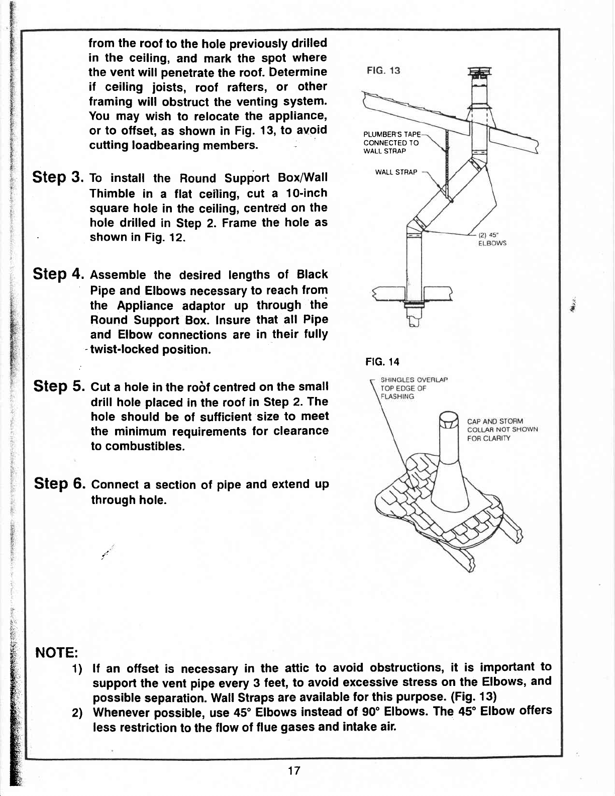
from the roof
to the
hole
previously
drilled
in the ceiling,
and mark the
spot
where
the vent
will
penetrate
the
roof.
Determine
if ceiling
joists,
roof
ratters,
or
other
framing
will
obstruct
the
venting
system.
You may
wish
to
relocate
the
appliance,
or
to
otfset,
as
shown
in
Fig.
13,
to avoid
cutting
loadbearing
members.
:
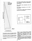
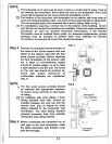
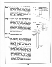
Step
3.
ro install
the Round Support
Box/Wall
Thimble
in
a flat
ceiling,
cut a
10-inch
square hole
in
the ceiling,
centred
on
the
hole
drilled
in
Step 2.
Frame
the
hole
as
.
shown in
Fig. 12.
Step
4. Assembte
the
desired
lengths
of
Black
Pipe and
Elbows
necessary
to
reach
from
the Appliance
adaptor
up
through
thd
Round
Support
Box. lnsure
that
all
Pipe
and Elbow
connections
are
in
their
fully
-
twist-locked
position.
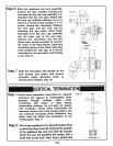
Step
5. Cut a hole in
the robf
centred
on
the small
drill hole
placed
in
the
roof
in
Step
2.
The
hole
should
be
ol sutficient
size
to
meet
the minimum
requirements
for clearance
to
combustibles.
I
Step
6.
Connect
a
section
of
pipe
and
extend
up
through hole.
NOTE:
1)
2)
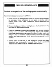
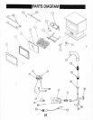
FIG, 14
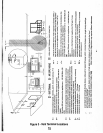
lf an offset
is
necessary
in the attic
to avoid
obstructions, it
is important
to
support
the vent
pipe
every
3
feet,
to avoid
excessive
stress on
the
Elbows,
and
possible
separation. Wall
Straps
are
available
for this
purpose. (Fig.
13)
Whenever
possible,
use
45'
Elbows
instead
of 90' Elbows.
The 45'
Elbow
otfers
less
restriction
to the
ftow
of
flue
gases
and intake
air.
PLUMBEH.S TAPE
CONNECTED TO
WALL STRAP
WALL
STRAP
17