


I
cATHEDRAL
cErLrNc
TNSTALLATToN
I
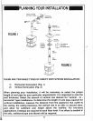
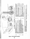
Step
1.
Follow
installation
Steps
1 and
2
under
Vertical
Terminations.
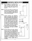
Step
2.
Using the
plumb
bob, mark
the centre-
line of
the
venting
system
on the
ceiling
and drill
a small
hole through
the ceiling
and roof
at
this
point.
From
the
roof,
locate
the
drill
hole and
mark the
outline
of
the
Cathedral
Ceiling
Support
Box.
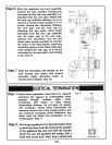
Step
3.
Remove
shingles
or
other
roof covering
as necessary
to
cut
the
rectangular
hole
for the
Support
Box. Cut
the
hole
118
larger
than
the
Support Box
outline.
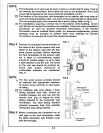
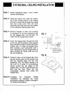
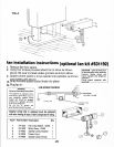
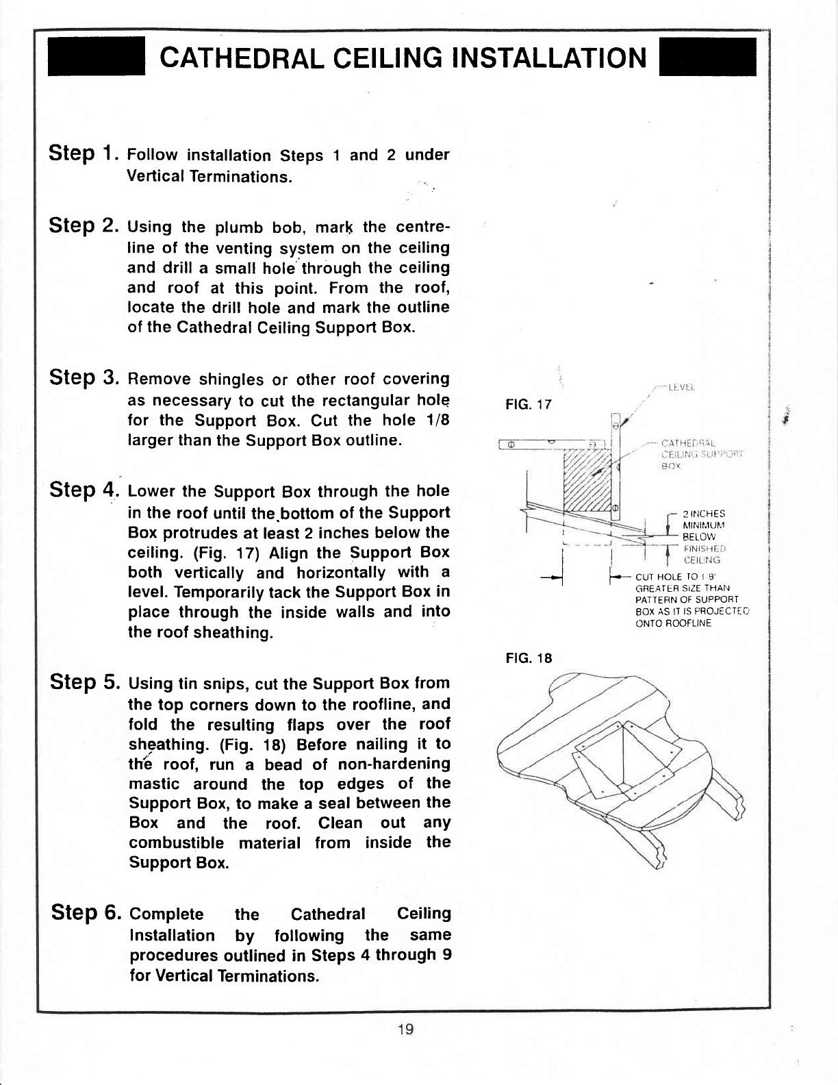
Step
4. Lower
the
Support
Box
through
the
hole
in the
roof
until
the.bottom
of the
Support
Box
protrudes
at least 2
inches
below
the
ceiling.
(Fig.
17)
Align
the
Support
Box
both vertically
and
horizontally
with
a
level.
Temporarily
tack the
Support
Box
in
place
through
the inside
walls and
into
the
roof
sheathing
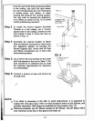
Step
5. Uslng tin
snips,
cut the
Support
Box
from
the top
corners
down to
the
roofline,
and
fold
the
resulting
flaps
over
the
roof
sheathing. (Fig.
18)
Before
nailing
it to
th:6 roof,
run
a bead
of
non-hardening
mastic
around
the
top
edges
of
the
Support
Box,
to make a seal
between
the
Box
and
the
roof.
Clean
out
any
combustible
material
from
inside
the
Support
Box.
Step
6. Complete
the
Cathedral
Ceiling
Installation
by following
the
same
procedures
outlined in Steps
4 through
9
for Vertical
Terminations.
FtG. 17
t
I
I
I
->l
I
_
3INCFIES
N'ilf{f,,rur.1
EELOV/
I
f--
CUI
HOLE
rO I
8
CJFE,qILF
SIZE
THAN
PATTERN OF SUPPOFIT
BOX
AS
IT
IS
PBOJECTi{:,
ONIO
ROOFLINE
FtG.
18