


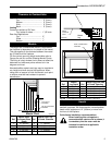
7
Pyromaster© H33BDVRRN/P
10004798
Installation
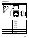
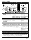
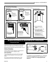
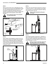
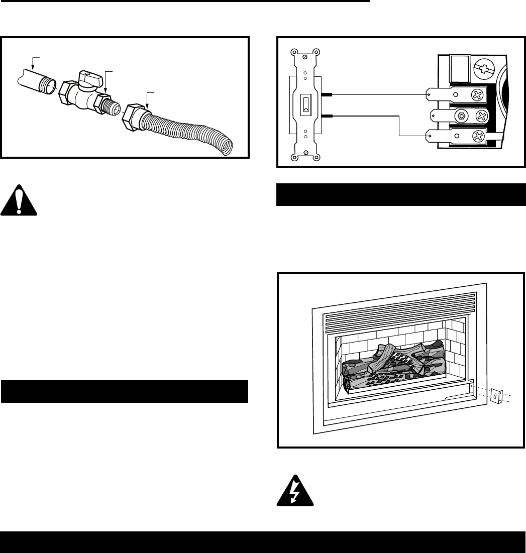
1. Thread the wiring through the holes on the end
panels of the fireplace. Take care not to cut the wire
or insulation on metal edges. Route the wire to a
conveniently located receptacle box.
2. Attach the wire to the ON/OFF switch and install the
switch into the receptacle box.
3. Connect the other ends of the wire to the gas
control valve. (Fig. 6)
Do not wire the remote ON/OFF wall
switch for the gas fireplace to the 120
volt power supply.
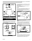
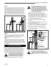
Alternate Switch Location
The remote switch can be installed on the front/side of
the access door. Simply mount the switch to the
bracket provided and screw the bracket to either side
of the frame, lining up the screws with the pre-punched
holes. (Fig. 7)
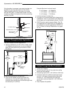
The gas control is equipped with a captured screw type
pressure test point, therefore it is not necessary to
provide a 1/8" test point up stream of the control.
When using copper or flex connector use only ap-
proved fittings. Always provide a union when using
black iron pipe so the gas line can be easily discon-
nected for burner or fan servicing. See gas specifica-
tion for pressure details and ratings.
The fireplace valve must not be subjected to any test
pressures exceeding 1/2 psi. Isolate or disconnect this
and any other gas appliance control from the gas line
when pressure testing.
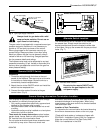
Remote ON/OFF Switch
Always check for gas leaks with a mild
soap and water solution. Do not use an
open flame for leak testing.
1/2” Gas Supply
1/2” NPT x 1/2” Flare
Shut-Off Valve
3/8” Flex Line
(From Valve)
FP297a
Fig. 5 Typical gas supply installation.
Fig. 7 Alternate switch location.
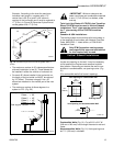
Your fireplace is approved to be vented either through
the side wall, or vertically through the roof.
• Only venting components specifically approved and
labelled for this fireplace may be used.
• Vent terminations shall not be recessed into a wall
or siding.
• Horizontal venting must be installed on a level plane
without any incline or decline.
There must not be any obstruction such as bushes,
garden sheds, fences, decks or utility buildings within
24" from the front of the termination hood.
Do not locate termination hood where excessive snow
or ice build up may occur. Be sure to check vent
General Venting Information–Termination Location
termination area after snow falls, and clear to prevent
accidental blockage of venting system. When using
snow blowers, make sure snow is not directed towards
vent termination area.
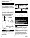
Location of Vent Termination
It is imperative the vent termination be located observing
the minimum clearances as shown on the next page.
*Check with local codes or in absence of same with
CSA-B149.1 Installation Codes (1991) for Canada or
follow the current National Fuel Gas Code, ANSI
Z223.1 for installations in the USA.
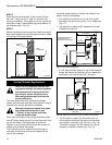
T
P
T
H
TH
T
P
Remote ON/OFF Switch
FP1218
Fig. 6 Remote switch wiring diagram.