


6
Pyromaster© H33BDVRRN/P
10004798
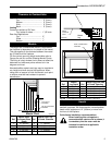
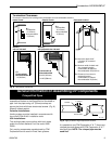
Noncombustible materials such as brick or tile may be
extended over the edges of the face of the fireplace.
DO NOT cover any vent or grille panels.
If a Trim Kit is going to be installed on the fireplace, the
brick or tile will have to be installed flush with the
edges of the fireplace.
Final Finishing
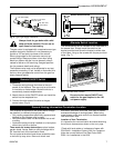
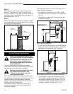
The gas pipeline can be brought in through the rear of
the appliance as well as the bottom. Knockouts are
provided on the bottom behind the valve to allow for the
gas pipe installation and testing of any gas connection.
It is most convenient to bring the gas line in from the
rear right side of the valve as this allows fan installation
or removal without disconnecting the gas line.
The gas line connection can be made with properly
tinned 3/8” copper tubing, 3/8” rigid pipe or an ap-
proved flex connector. Since some municipalities have
additional local codes, it is always best to consult your
local authority and the National Fuel Gas Code, ANSI
Z223.1 in the USA or the CSA-B149.1 installation
code.
Gas Line Installation
When purging gas lines, the front win-
dow frame assembly must be removed.
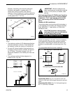
1. Choose the unit location.
2. Place the unit into position and secure it to the floor
with 1¹⁄₂” (38mm) screws, or nails. The holes to
secure the unit to the floor are located just behind
the access door grille on the left and right side of the
unit.
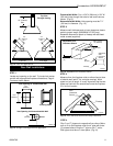
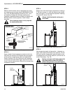
3. Frame in the fireplace with a header across the top.
It is important to allow for the finished wall face when
setting the depth of the frame.
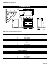
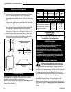
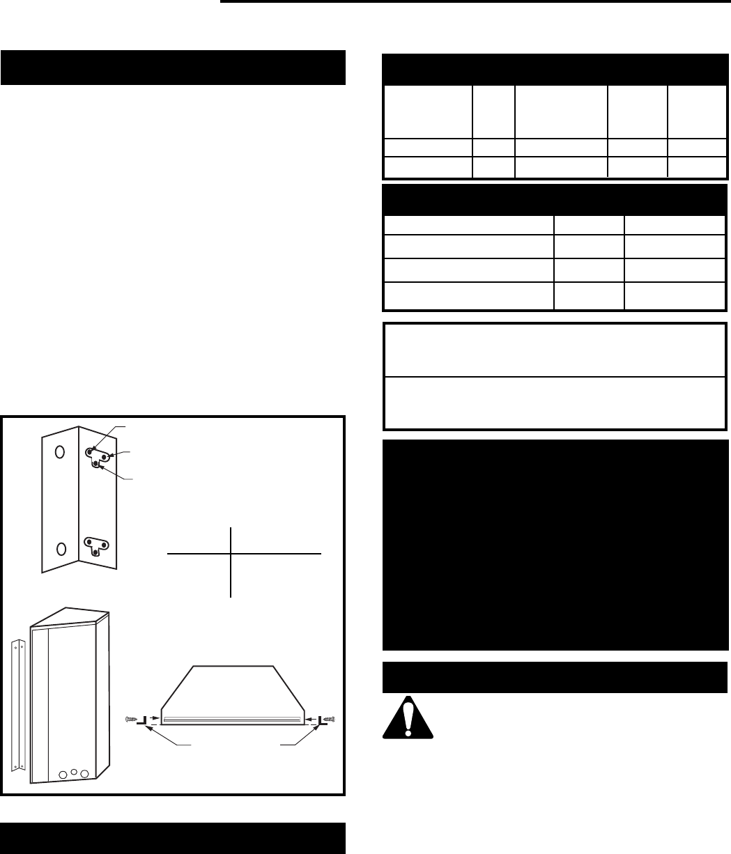
4. Attach the fireplace to the frame using the adjustable
frame drywall strips (located behind the access door
for shipping). Preset the depth to suit the facing
material of the wall. The strips are adjustable to 1/2”
(13mm), 5/8” (16mm), or 3/4” (19mm). (Figs. 3 & 4)
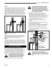
5. Screw through the slotted holes in the drywall strip
and into the pre-drilled holes in the fireplace side.
Measure from the face of the fireplace to the face of
the drywall strip to confirm the final depth.
Framing and Finishing
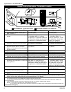
Natural LP (Propane)
Minimum Inlet Pressure 5.5” wc 11” wc
Maximum Inlet Pressure 14” wc 14” wc
Manifold Pressure 3.5” wc 10” wc
Gas Inlet and Manifold Pressures
H33BDVRRN/P
Certified To
ANSI Z21.88b-1999 / CSA 2.33b-M99
Vented Gas Fireplace Heaters
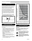
High Elevations
Input ratings are shown in BTU per hour and are
certified without deration for elevations up to
4,500 feet (1,370m) above sea level.
For elevations above 4,500 feet (1,370m) in USA,
installations must be in accordance with the
current ANSI Z223.1 and/or local codes having
jurisdiction.
In Canada, please consult provincial and/or local
authorities having jurisdiction for installations at
elevations above 4,500 feet (1,370m).
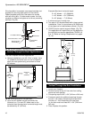
C
B
A
Adjustable Drywall Strip
(Nailing Flange)
Adjustable 1/2”,
5/8” & 3/4”
Spacing
FP1023
Screw Drywall
Position Depths
A 1/2” / 13mm
B 5/8” / 16mm
C 3/4” / 19mm
Fig. 4 Adjustable drywall strip (nailing flange).
Gas Specifications
Max. Min.
Model Fuel Gas Control Input Input
BTU/h BTU/h
H33BDVRRNNat Millivolt 15,000 10,500
H33BDVRRPProp Millivolt 15,000 11,250