


12
Pyromaster© H33BDVRRN/P
10004798
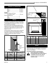
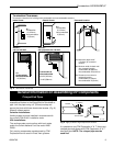
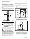
STEP 5
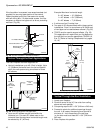
Guide the vent termination 4” collar into the 4” pipe
then the 7” collar into the 7” pipe. Do not force the
venting into position. If the pipes do not line up with the
termination collars, disassemble pipes and reattach to
the fireplace collar. (Fig. 16)
STEP 6
Secure fireplace to floor through floor holes and adjust-
able frame drywall strip (nailing flange) to frame. (Refer
to Framing & Finishing Section).
Finished
Wall
Vent
Termination
FP1005b
Fig. 16 Side view of final unit location.
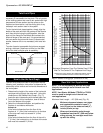
Since it is very important that the vent-
ing system maintain its balance between
the combustion air intake and the flue
gas exhaust, certain limitations as to
vent configurations apply and must be
strictly adhered to.
The Vent Graph shows the relationship between
vertical and horizontal side wall venting and will help to
determine the various dimensions allowable.
Minimum clearance between vent pipes
and combustible materials is one
1"(25mm) on top, bottom and sides
unless otherwise noted.
When vent termination exits through foundations less
than 20" below siding outcrop, the vent pipe must flush
up with the siding. It is always best to locate the
fireplace in such a way that minimizes the number of
offsets and horizontal vent length.
The horizontal vent run refers to the total length of
vent pipe from the flue collar of the fireplace to the
face of the outer wall.
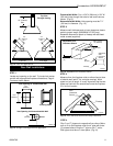
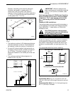
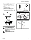
Vertical Sidewall Applications
Horizontal plane means no vertical rise exists on this
portion of the vent assembly.
• The maximum horizontal vent run is 20 ft. (6100
mm) when the vertical vent rise is 7¹⁄₂ ft. (2286 mm).
(Fig. 17)
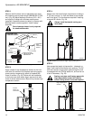
• The maximum number of 90° elbows per side wall
installation is three (3).
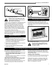
• If a 90° elbow is fitted directly on top of the fireplace
flange, the maximum horizontal vent run before the
termination or a vertical rise is 36" (914 mm).
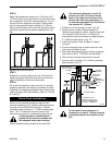
• If a 90° elbow is used in the horizontal vent run
(level height maintained) the maximum horizontal
vent length is reduced by 36" (914 mm). (Fig. 18)
This does not apply if the 90° elbows are used to
increase or redirect a vertical rise. (Fig. 19)
Side View
Maximum
3’ (914mm)
7TDVRT90
Elbow
CFM142
Fig. 18 Maximum horizontal vent run before termination.
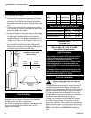
Maximum
20 ft. (6100mm)
90"
(2286mm)
7TDVRT90
Elbow
15 ft.
(4572mm)
48"
(1220mm)
12"
(305mm)
Vertical Dimension 7¹⁄₂
ft. Minimum when
Horizontal Run is 20 ft.
Fig. 17 Maximum dimensions.