


11
Pyromaster© H33BDVRRN/P
10004798
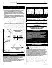
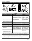
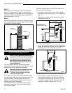
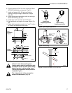
STEP 1
Locate vent opening on the wall. To locate hole center
consult with appropriate fireplace dimensions, Page 4.
Frame as shown below.
Combustible Walls: Cut a 10³⁄₈”H (264 mm) x 9³⁄₈” W
(240 mm) hole through the exterior wall and frame as
shown. (Fig.13)
Noncombustible Walls: Hole opening must be 7¹⁄₂”
(190 mm) in diameter. (Fig. 13)
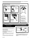
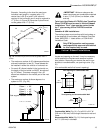
STEP 2
Measure wall thickness and cut zero clearance sleeve
parts to proper length (MAXIMUM 12”/305 mm).
Assemble sleeve and attach to firestop with #8 sheet
metal screws (supplied).
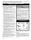
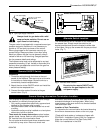
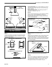
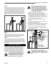
Rear Wall Installations
20" (508mm)
Max.
20"
(508mm)
Max.
45
¡
20"
(508mm)
Max.
45
¡
Top View
Straight Venting
Top View Cross Corner Vent
to the Left
Top View Cross Corner Vent
to the Right
Fig. 12 Rear vent applications.
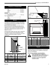
Max. Length
12” (294mm)
#8 Screws
(2)
#8 Screws
(2)
Adjustable Zero
Clearance Sleeve
Adjustable
Zero
Clearance
Sleeve
Firestop
H8
Screws
ZCS101
Fig. 14 Adjustable zero clearance sleeve.
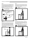
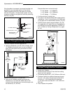
STEP 3
Measure from the fireplace collar or elbow face to face
of outside wall (add 2” for vent pipe overlap). Mark
pipes and cut to length. It is very important that the two
pipes are flush with the outside wall once the fireplace
is in its final location.
Zero
Clearance
Sleeve
Firestop
CFM133
Fig. 15 Zero clearance sleeve and firestop installation.
STEP 4
Slip 4” and 7” pipes onto respective flue collars. Make
sure to fix to the fireplace collar the 4” pipe with three
(3) screws before fixing the 7” pipe on the 7” collar.
Both pipes must be on a level plane. (Fig 16)
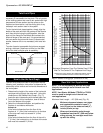
Vent Opening for Combustible Wall
9³⁄₈”
(240mm)
10³⁄₈”
(254mm)
Framing Detail
7¹⁄₂”
(190mm)
Vent Opening for Noncombustible Wall
VO584-100
Fig. 13 Straight out through the wall application.