


6
DVRTSB Bay Window Fireplace
10003848
Top of Unit to Ceiling ......................................... 36” (914 mm)
Front of Unit to Combustibles ............................ 36” (914 mm)
Appliance
Top ..................................................(0”) 0 mm to stand-off
Bottom ................................................................
(0”) 0 mm
Back .........................................
(1/2”) 13 mm to rear panel
Side Wall ...........................................................
(0”) 0 mm.
(behind side glass panel)
Venting
Concentric sections of DV Vent
Top, bottom & sides ..........................................
(1”) 25 mm
Non-concentric sections of DV Vent
Side and bottom ................................................
(1”) 25 mm
Top ....................................................................
(2”) 51 mm
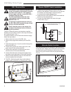
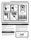
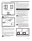
1. Choose the unit location.
2. Place the unit into position and secure it to the floor
with 1¹⁄₂” (38 mm) screws, or nails. The holes to
secure the unit to the floor are located just behind
the access door grille on the left and right side of the
unit.
3. Frame in the fireplace with a header across the top.
It is important to allow for the finished wall face when
setting the depth of the frame.
4. Drywall (sheetrock) or wood material may be placed
with a zero clearance to the top edges of the appli-
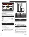
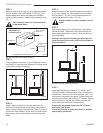
Cold climate installation recommendation:
When installing this unit against a non-
insulated exterior wall or chase, it is
mandatory that the outer walls be insulated
to conform to applicable insulation codes.
Framing and Finishing
Hearth
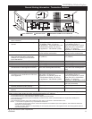
Mantels
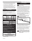
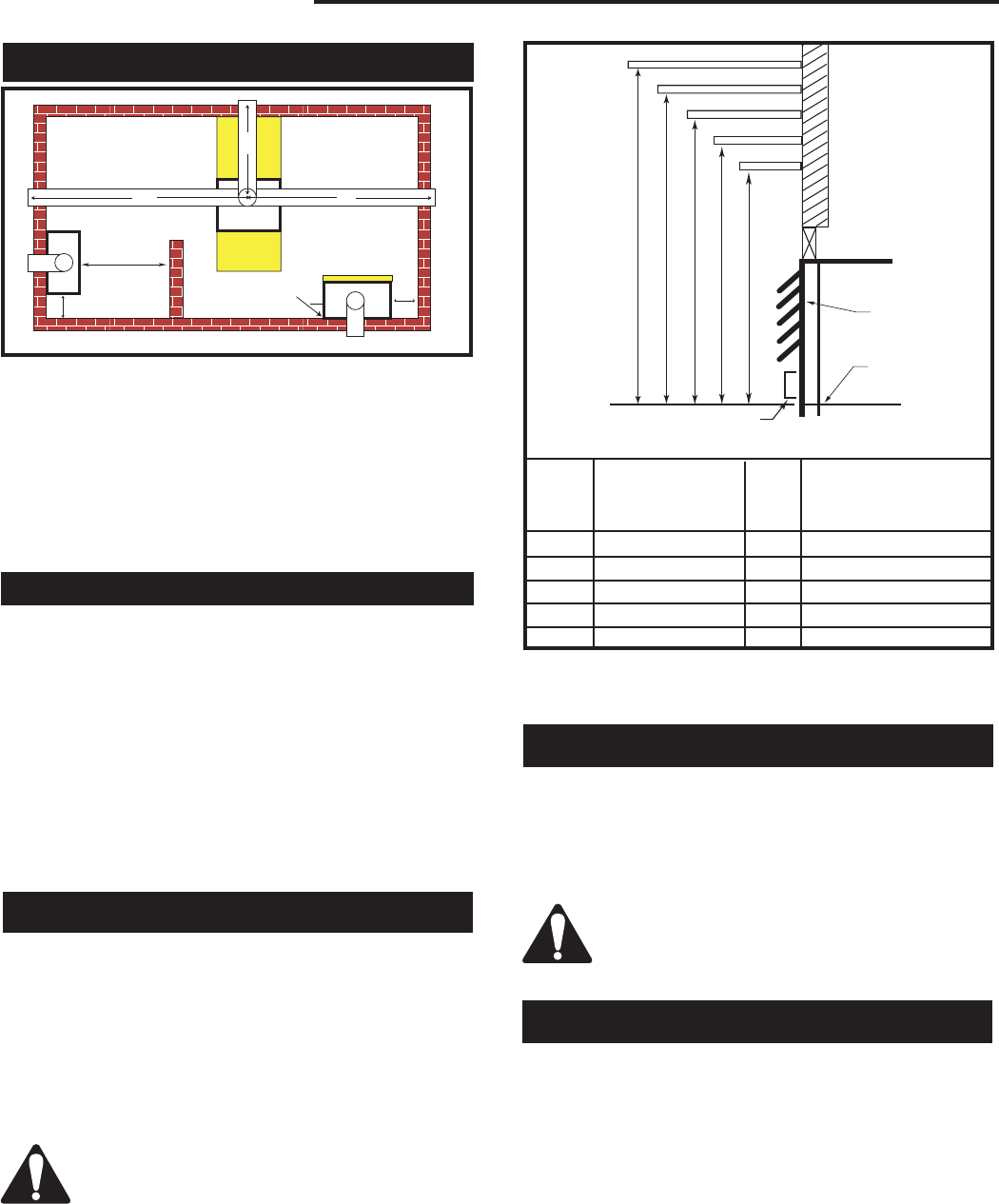
The height that a combustible mantel is fitted above the
fireplace is dependent on the depth of the mantel. This
also applies to the distance between the mantel leg (if
fitted) and the fireplace.
For the correct mounting height and widths refer to
Figure and the Mantel Chart below.
Noncombustible mantels and legs may be installed at
any height and width around the appliance.
When using paint or lacquer to finish the
mantel, such paint or lacquer must be heat
resistant to prevent discoloration.
Clearance to Combustibles
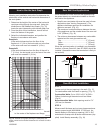
Mantel Chart
Mantel Shelf Mantel from Top
Ref. or Breast Plate Ref. of Comb. Chamber
Depth
V 10” (254 mm) A 19” (483 mm)
W 8” (203 mm) B 17” (432 mm)
X 6” (152 mm) C 15” (381 mm)
Y 4” (101 mm) D 13” (330 mm)
Z 2” (51 mm) E 11” (279 mm)
A B C D E
V
W
X
Y
Z
Fireplace
CFM146
DV Mantel Chart
7/5/01 sta
CFM146
NOTE: The above mantel shelf chart will be applied
for the front and two sides of the fireplace.
Top Louvre
Assembly
Top of
Combustion
Chamber
Bottom of Door
Trim
Fig. 4 Combustible mantel minimum installation.
A hearth is not mandatory but is recommended for
aesthetic purposes. We recommend a noncombustible
hearth which projects out 12” (305mm) or more from
the front of the fireplace.
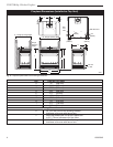
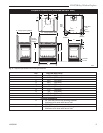
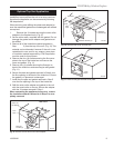
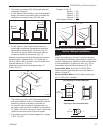
Locating Your Fireplace
A. Wall Location (Fig. 1)
Y (Minimum distance between a glass panel and a parallel
wall = 3’ (914 mm)
Z (Minimum distance between edge of a glass panel and
an adjacent wall = 2-3/4” (70 mm)
B. Island Location (FIg. 1)
X (Maximum length of horizontal venting = 20’ (6.1 m).
Refer to the venting section of this manual for specific
dimensions.
X
X
X
Y
Y
Y
Z
A
A
B
FP1374
Fig. 1 Locating gas fireplace.