


18
DVRTSB Bay Window Fireplace
10003848
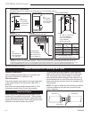
1. Locate your fireplace.
2. Plumb to center of the (4”) flue collar from ceiling
above and mark position.
3. Cut opening equal to 9
³⁄₈” x 9³⁄₈” (240 x 240 mm).
4. Proceed to plumb for additional openings through
the roof. In all cases, the opening must provide a
minimum of 1” (25 mm) clearance to the vent pipe,
i.e., the hole must be at least 9³⁄₈” x 9³⁄₈” (240 x
240mm).
5. Place fireplace into position.
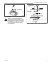
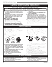
6. Place firestop(s) #7DVFS or Attic Insulation Shield
#7DVAIS into position and secure. (Fig. 34)
7. Install roof support (Fig. 32) and roof flashing making
sure upper flange is below the shingles. (Fig. 33)
8. Install appropriate pipe sections until the venting is
above the flashing. (Fig. 33)
9. Install storm collar and seal around the pipe. (Fig.
33)
10. Add additional vent lengths for proper height. (Fig.
31)
The enlarged ends of the vent section always
face downward.
11. Apply high temperature sealant to 4” and 7” collars
of vertical vent termination and install.
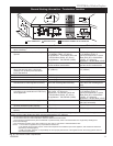
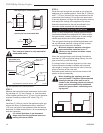
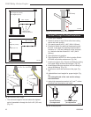
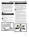
Vertical Through-The-Roof Installation
• The minimum height of the vent above the highest
point of penetration through the foof is 24” (610 mm)
(Fig. 31)
Max. 10' (3m)
Max. Height 40' (12.2m)
Min. Height 8' (2.4m)
Max.
Height 40' (12.2m)
Min.
Height 8' (2.4 m)
Max. 10' (3m)
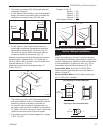
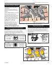
Support straps
every 36" (914mm)
FP1387
Fig. 29 Support for horizontal runs.
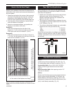
1
2
3
4
1
2
3
4
1 + 2 + 3 + 4 = 270
o
FP1389
Fig. 30 Maximum elbow usage.
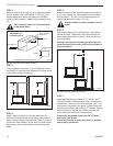
Min.
2' (610 mm)
FP1389
Fig. 31 Minimum termination to roof clearance.
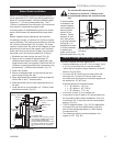
FP1184
Typical roof/ceiling
support apps.
Typical Roof Sup-
port Application
Typical Ceiling Sup-
port Application
FP1184
Fig. 32 Venting supports.