


15
DVRTSB Bay Window Fireplace
10003848
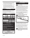
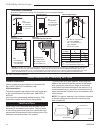
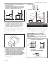
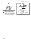
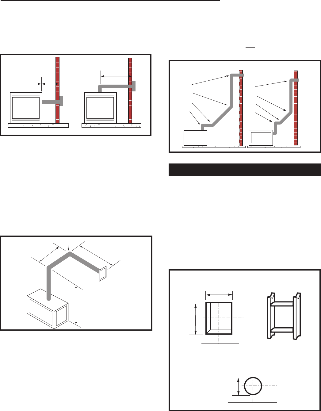
• The maximum number of 90° elbows per side wall
installation is three (3).
• If a 90° elbow is fitted directly on top of the fireplace
flange, the maximum horizontal vent run before the
termination or a vertical rise is 36” (914 mm).
Max. 20"
(508mm)
Max. 36"
(914mm)
FP1381
Fig. 20 Maximum horizontal vent run.
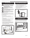
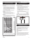
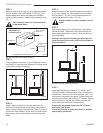
• If a 90° elbow is used in the horizontal vent run
(level height maintained) the maximum horizontal
vent length is reduced by 36” (914 mm). (Fig. 21)
This does not apply if the 90° elbows are used to
increase or redirect a vertical rise. (Fig. 21)
Example: According to the chart the maximum horizon-
tal vent length in a system with a 7.5’ vertical rise is
20’ (6 m) and if a 90° is required in the horizontal vent it
must be reduced to 17’ (5.2 m).
Dimension A plus B must not be greater than 17’
(5.2m). (Fig. 21)
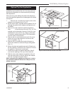
• The maximum number of 45° elbows permitted per
side wall installation is two (2). These elbows can be
installed in either the vertical or horizontal run.
• For each 45° elbow installed in the horizontal run,
the length of the horizontal run MUST be reduced by
18” (45cm). This does not apply if the 45° elbows are
installed in the vertical part of the vent system.
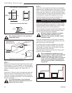
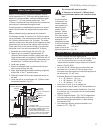
• The maximum number of elbow degrees in a system
is 270°. (Fig. 22)
7'6"
(2286mm)
A
B
A + B = 17' Max.
(5.2m)
90°
FP1382
Fig. 21 Maximum vent run with elbows.
1
2
3
4
1 + 2 + 3 + 4 = 270
o
1
2
3
4
FP1383
Fig. 22 Maximum number of elbows allowed.
Example: In Fig. 22
Elbow 1 = 90°
Elbow 2 = 45°
Elbow 3 = 45°
Elbow 4 = 90°
Total Angular Variation = 270°
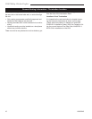
Vertical Sidewall Installation
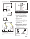
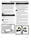
STEP 1
Locate vent opening on the wall. It may be necessary
to first position the fireplace and measure to obtain hole
location. Depending on whether the wall is combustible
or noncombustible, cut opening to size. (Fig. 23) For
combustible walls first frame in opening. (Fig. 23)
Combustible Walls:
Cut a 9³⁄₈”H x 9³⁄₈”W (240 x
240mm) hole through the exterior wall and frame as
shown in Figure 23.
Noncombustible Walls
(Fig. 23): Hole opening must
be 7¹⁄₂” (190 mm) in diameter.
VO584-100
Vent Opening
2/99 djt
Vent Opening for Combustible Wall
9³⁄₈”
(240 mm)
9³⁄₈”
(240 mm)
Framing Detail
Opening for Noncombustible Wall
7¹⁄₂”
(190 mm)
VO584-100
Fig. 23 Locate vent opening on wall.