


14
DVRTSB Bay Window Fireplace
10003848
STEP 5
Guide the vent through the vent hole as you place the
appliance in its installed position. Guide the 4” (102mm)
and 7” (175 mm) collars of the vent termination into the
outer ends of the venting. Do not force the termination.
If the vent pipes do not align with the temination remove
and realign the venting at the appliance flue collars.
Attach the termination to the wall as outlined in the
instruction sheet supplied with the termination.
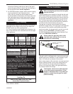
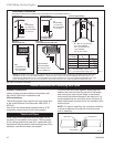
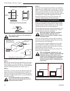
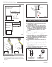
Vertical Sidewall Applications
VO584-100
Vent Opening
2/99 djt
Vent Opening for Combustible Wall
9³⁄₈”
(240 mm)
10³⁄₈”
(265 mm)
Framing Detail
Opening for Noncombustible Wall
7¹⁄₂”
(190 mm)
VO584-100
Fig. 17 Locate vent opening on wall.
Zero clearance sleeve is only required for
combustible walls.
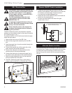
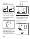
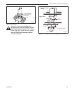
ZCS101
Zero Clearance Sleeve
3/11/99 djt
Max. Length 12”
(305mm)
#8 Screws (2)
#8 Screws
(2)
Adjustable Zero Clearance Sleeve
ZCS101
#8 Screws (2)
Firestop
Adjustable Zero
Clearance Sleeve
Fig. 18 Adjustable zero clearance sleeve.
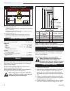
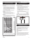
Since it is very important the venting system maintain
its balance between the combustion air intake and the
flue gas exhaust, certain limitations as to vent configu-
rations apply and must be strictly adhered to.
The vent graph showing the relationship between verti-
cal and horizontal side wall venting will help to deter-
mine the various dimensions allowable.
Minimum clearance between vent pipes
and combustible materials is one 1”
(25mm) on top, bottom and sides unless
otherwise noted.
When the vent termination exits through foundations
less than 20” (508 mm) below siding outcrop, the vent
pipe must flush up with the siding.
It is always best to locate the fireplace in such a way
that minimizes the number of offsets and horizontal
vent length of vent pipe from the flue collar of the fire-
place to the face of the outer wall.
Horizontal plane means no vertical rise exists on this
portion of the vent assembly.
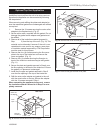
When installing the appliance as a rear
vent unit the 90° Transition Elbow attached
directly to the rear of the unit is not in-
cluded in the following criteria and calcula-
tions, and unless specifically mentioned
should be ignored when calculating vent-
ing layouts.
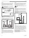
FP1380
Fig. 19 Maximum number of 90· elbows per sidewall.
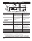
STEP 3
Measure the horizontal length requirement for the vent-
ing including a 2” (51 mm) overlap, i.e. from the elbow
to the outside wall face plus 2” (51 mm) (or the distance
required if installing a second 90° elbow. (Fig. 17)
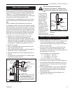
STEP 4
Install the 4” (102 mm) vent to the appliance collar and
secure with three (3) sheetmetal screws. Install the 7”
(175 mm) vent pipe to the appliance collar and secure
with three (3) sheet metal screws. It is not necessary to
seal this connection.
It is critical that there is no downward
slope away from the appliance when con-
necting the vent or elbow.