7
DV360/580 Series Direct Vent Gas Fireplace
20010667
Framing And Finishing
Check fireplace to make sure it is levelled
and properly positioned.
To mount the appliance: Choose the location.
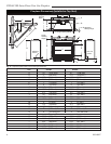
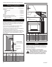
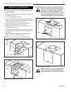
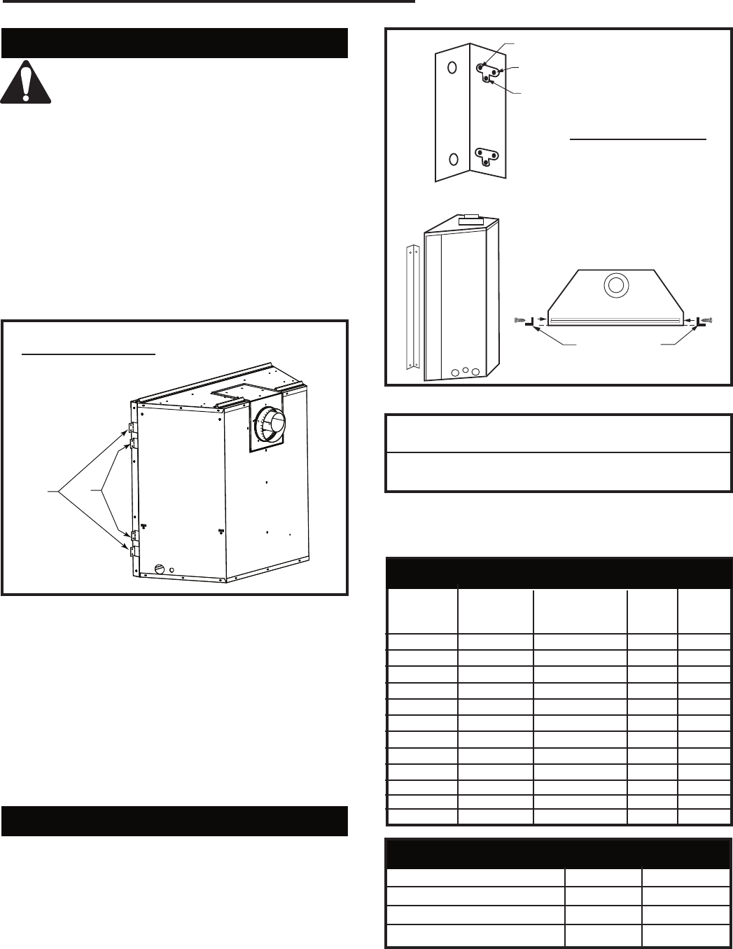
DV360 (Fig. 5)
1. This unit comes with four (4) flanges pre-mounted
on both sides of the fireplace to allow two different
drywall thicknesses to be used. Flange “A” is for 1/2”
drywall while flange “B“ is for 5/8” drywall.
2. Bend the desired flanges out 90° on both sides of
the fireplace. Slide the fireplace into the framed
opening until the flanges contact the front surfaces
of the framing. Level the unit and secure it firmly in
place.
A
B
FP1539
flange location
12/04
Flange Drywall
Position Depth
A 1/2” / 13 mm
B 5/8” / 16 mm
Flange Location for
Desired Drywall Depth
FP1539
Fig. 5 Drywall flange location for DV360.
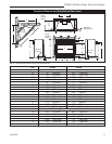
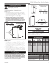
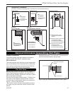
DV580 (Fig. 5a)
1. Nailing flanges are supplied with the fireplace (found
on the fireplace hearth). To level the box and secure
it firmly in place, remove the nailing flanges from
the hearth and install at the sides of the fireplace as
shown in Figure 5a.
2. Screw through the slotted holes in the drywall strip
and into pre-drilled holes in fireplace side. Measure
from face of fireplace to the face of the drywall strip
to confirm the final depth.
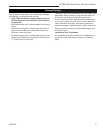
Final Finishing
Noncombustible materials such as brick or tile can be
extended over the edges of the face of the fireplace.
Do not cover the window frame assembly, any vent,
louvre assembly top or louvre assembly bottom. If
a Trim Kit is to be installed, brick and tile will have to be
installed flush with the side of this appliance.
FP1023
side nailing flange
1/27/00 djt
A
B
C
Adjustable Drywall Strip
(Nailing Flange)
Flange Drywall
Position Depth
A 1/2” / 13 mm
B 5/8” / 16 mm
C 3/4” / 19 mm
Adjustable
1/2”, 5/8” & 3/4”
Spacing
FP1023
Fig. 5a Adjustable drywall strip (nailing flange) for DV580.
DV360 / DV580
Certified To
ANSI Z21.88-2002/CSA 2.33-2002
Vented Gas Fireplace Heater
For units:
GFDN4L1, GFDE4L1, GFDI4L1, GFDL4L1
GFDN4P0, GFDE4P0, GFDI4P0
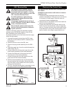
Gas Specifications
MAX. MIN.
GAS INPUT INPUT
MODEL FUEL CONTROL B.T.U.H B.T.U.H.
DV360RN Natural Gas Millivolt Hi/Lo 30,000 18,500
DV360RP Propane Millivolt Hi/Lo 30,000 17,000
DV360EN Natural Gas 24 Volt Hi/Lo 30,000 18,500
DV360EP Propane 24 Volt Hi/Lo 30,000 20,000
DV360RFN Natural Gas Comfort Control 30,000 20,000
DV360RFP Propane Comfort Control 30,000 21,000
DV580RN Natural Gas Millivolt Hi/Lo 38,000 26,500
DV580RP Propane Millivolt Hi/Lo 38,000 27,000
DV580EN Natural Gas 24 Volt Hi/Lo 38,000 26,500
DV580EP Propane 24 Volt Hi/Lo 38,000 27,000
DV580RFN Natural Gas Comfort Control 38,000 26,500
DV580RFP Propane Comfort Control 38,000 27,000
Gas Inlet and Manifold Pressures
Natural LP (Propane)
Minimum Inlet Pressure 5.5” w.c. 11.0” w.c.
Maximum Inlet Pressure 14.0” w.c. 14.0” w.c.
Manifold Pressure 3.5” w.c. 10.0” w.c.


