


15
Vermont Castings Seville
30001490
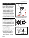
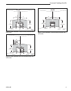
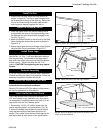
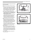
Install the Fan
1. Position the Fan body within the Rear Shroud as
shown in Figure 20. The Fan’s upper flange should
be located behind the lip of the opening. Secure the
Fan to the Shroud using five sheet metal screws
and single star washer supplied with the kit.
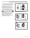
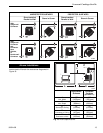
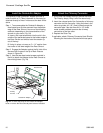
Install the Rheostat Switch
1. Install the Switch within the Switch Bracket that is
provided with the stove in the Hardware Bag. Use
the Retainer Nut and Control Knob provided in the
Fan Kit. (Fig.21-1)
2. Attach the Switch Bracket to the left side of the Rear
Shroud using two sheet metal screws as shown in
Figure 21-2.
3. Secure the fan wire harness to the back of the Shroud
using the Wire Tie plug as shown in Figure 21-2.
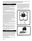
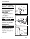
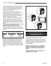
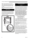
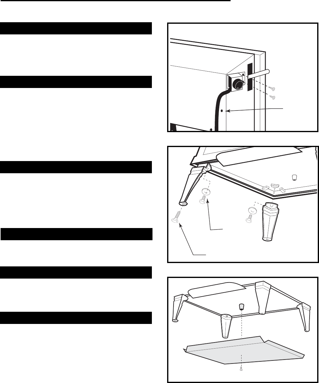
Install Stove Legs
Install legs before removing the stove from the pallet.
Use the four 1/4 -20x 1” hex head bolts with washers
from the parts bag. The shoulder of the legs should
seat within the locator tabs cast into the stove bottom
at each corner. Tighten the bolts with the 7/16”
wrench. CAUTION: Overtighening can strip tapped
threads.
Pedestal Assembly
If you are using the Seville Pedestal option, assemble
it before removing the stove from the pallet. Follow the
assembly instructions included with the kit.
Remove the Stove from the Pallet
Caution. The Seville is very heavy. Do not attempt
to handle the stove without assistance.
Carefully lift the stove off of the pallet and manuever it
as close as possible to its final position.
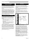
Install the Bottom Heat Shield
The #1889 Bottom Heat Shield must be used in the
U.S. and Canada in any installation on a floor that is
not comprised of unpainted cement on earth. It is not
required for use with the Pedestal option.
1. Remove the 1/4-20x 1/2" phillips screw from the
central mounting boss in the stove bottom. (Fig. 23)
2. Mount the bottom heat shield to the stove bottom
using the same phillips head screw previously re-
moved. The corners of the shield will butt against the
cast leg locators at each corner of the stove bottom.
Fig. 21-2 Attach the Rheostat Switch and Wire Tie.
Insert Wire
Tie Plug
Here
ST462
Fig. 22 Attach the Stove Legs and Leg Levellers
1/4-20 X 1” Leg
Bolt and Washer
Leg Leveller
ST466
Fig. 23 Attach the Bottom Heat Shield to the boss in the
center of the stove bottom.
1/4-20 x 1/2” Pan Head Screw
ST465