


12
Vermont Castings Seville
30001490
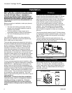
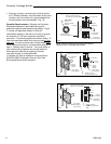
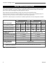
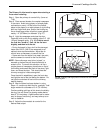
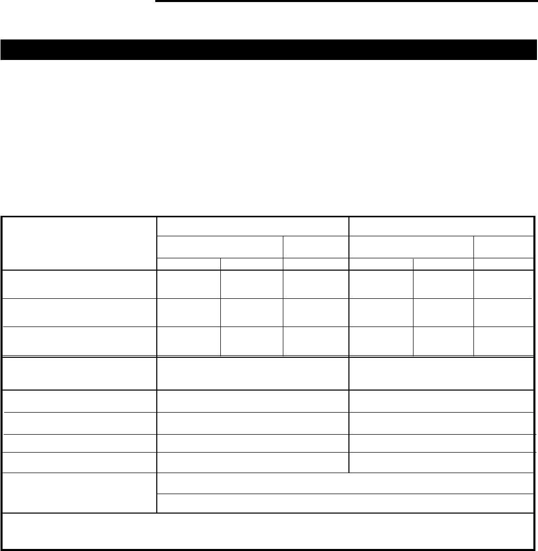
Seville 1635 Clearance Chart
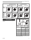
Use the chart below together with the diagrams on the next page to determine the minimum clearance required for
your particular installation. In any case, it is always advisable to locate the stove as far away from walls as pos-
sible in order to take full advantage of the radiant properties of cast iron.
Stove clearances are measured between the steel rear shroud and the combustible surface.
Chimney Connector clearances are measured between the connector surface and the combustible surface. For
Douible-wall Chimney Connector, use the manufacturer’s listed clearance specification.
Use NFPA 211 default clearance or manufacturer’s installation specifications for those configurations not tested.
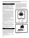
UNPROTECTED SURFACES PROTECTED SURFACES
Side Rear Corner Side Rear Corner
With Single-wall Connector
With Single-wall Connector
and Connector Heat Shields
With Double-wall Connector
STOVE CLEARANCE
Without Connector Heat Shields
With Connector Heat Shields
CHIMNEY CONNECTOR
CLEARANCE
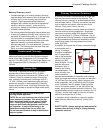
* A distance of 48" must be maintained between the stove and moveable combustible items such as drying
clothes, furniture, firewood, etc.
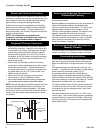
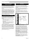
Corner
Installation
Parallel Installation
Corner
Installation
Parallel Installation
UNPROTECTED SURFACE / Vertical PROTECTED SURFACE / Vertical
FRONT CLEARANCE
TO COMBUSTIBLES*
ALL INSTALLATIONS
48" (1219mm)
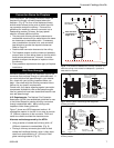
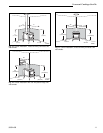
UNPROTECTED SURFACE / Horizontal PROTECTED SURFACE / Horizontal
Single-wall Connector
A 18”
(457mm)
B 15”
(381mm)
C 12”
(305mm)
G 14”
(357mm)
H 10”
(254mm)
I 6”
(152mm)
D 13”
(330 mm)
E 8”
(203mm)
F 6”
(152mm)
Not
Tested
10” (254mm)
8” (203mm)
8” (203mm)
18” (457mm) 12” (305mm)
8” (203mm)
G 14”
(357mm)
H 10”
(254mm)
I 6”
(152mm)
J 12”
(305mm)
K 6”
(152mm)
L 4”
(102mm)
Not
Tested
Not
Tested
Table 1. Approved Seville Clearances.