


14
Vermont Castings Seville
30001490
You will need the following tools to assemble the Seville:
• 7/16" open end wrench • safety glasses & gloves
• flat head screwdriver • power drill w/ 1/8" (3mm) bit
• stub handle phillips screwdriver
Unpack the Stove
1. Remove the shipping straps and plastic wrap.
2. Inspect the stove and contents for shipping damage
or missing parts. Immediately notify your dealer of
any damage. Do not install this stove if any damage
is evident or any parts are missing.
Hardware Bag contents:
• Stove Legs, 4
• Fan Switch Bracket (for use with optional fan)
• 1/4-20 x 1” hex head Leg Bolts with washers, qty 4
• #10 x 1/2" sheet metal screws, qty 2
• Owner's Registration Card
• Touch-up Paint (Porcelain enamel stoves only)
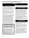
3. Remove the Top Plate from the stove body by lifting
up and away. Set it aside for replacement after the
stove has been positioned and connected to the
chimney.
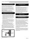
Optional Fan Kit 2960
Install the Fan Kit within the Rear Shroud before you
remove the stove body from the shipping pallet.
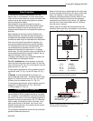
To test the fan operation before installation:
1. Connect the power cord to a three prong outlet.
2. Turn the rheostat switch ON.
3. Apply heat to the snapstat. The fan will operate
when the snapstat reaches 90˚F.
If the Control is left in the ON position, the fan will shut
off when the snapstat temperature falls below 90˚.
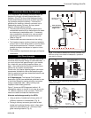
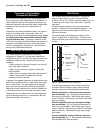
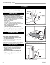
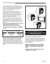
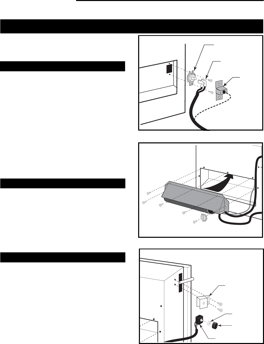
Install the Snapstat
1. Disconnect the leads from the Snapstat terminals.
2. Use pliers to remove the retainer ring from the
Snapstat Cover and slip the cover off the wire
harness. Discard cover.
3. Reconnect the wire leads to the Snapstat Plate.
4. Using two sheet metal screws from the fan kit,
attach the Snapstat Plate to the Inner Shroud as
indicated in Figure 19.
Assembly
Fig. 19 Install the Snapstat.
Snapstat
Rear Shroud
Snapstat
Cover
(Discard)
Leads
ST464
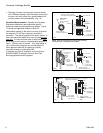
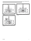
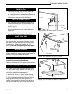
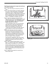
Fig. 20 Install the Fan body into the Rear Shroud.
ST462
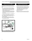
Switch Bracket
Switch Box
Retainer Nut
Control Knob
ST463
Fig. 21-1 Install the rheostat switch.