


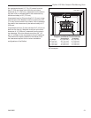
20
Defiant 1610 Non-Catalytic Woodburning Stove
30002850
Set Up Your Stove
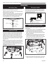
Cast iron stoves are heavy, and it will take two to four
people to move your Defiant into position.
Wipe the protective coating of oil from the griddle with a
clean dry rag or a paper towel.
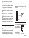
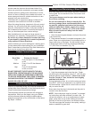
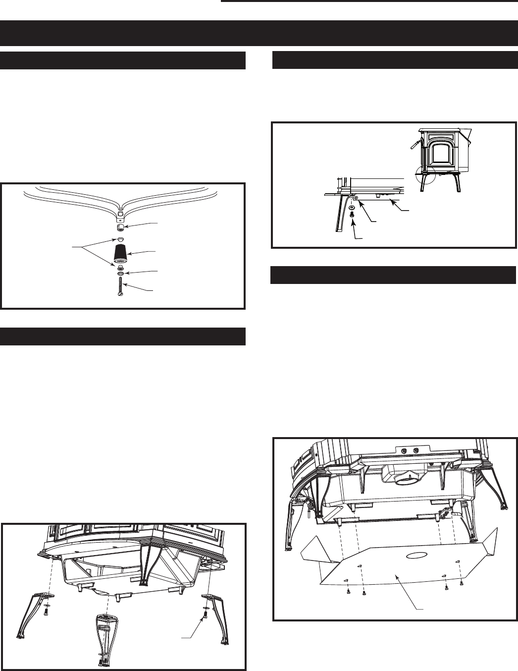
Install the handle on the griddle. Slip the bolt through a
washer, a nylon bushing, then through the handle and
the other bushing, then through the steel spacer and
into the griddle tab. (Fig. 19) Tighten securely.
Assembly
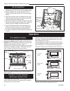
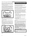
Install Stove Legs
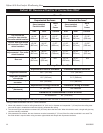
Remove and discard the four large slot-head screws
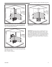
from the stove bottom. Install the stove legs (Fig. 20)
using the hex head bolts from the parts bag. Use 3/8”
washers with all four legs; the door handle holder at-
taches between the right front leg and the stove body.
Position the holder so the hole that accepts the handle
hub faces out from the right side of the stove. Tighten
the bolts firmly.
NOTE: It is usually most convenient to leave the stove
on its shipping pallet and swing one corner of the stove
at a time off the pallet to attach each leg. Be sure to
support the stove well (i.e. with wooden blocks) until all
four legs are secured to the stove.
CAUTION: Overtightening can strip tapped threads.
Leg Bolt and
Washer
ST858
Fig. 20 Attach the stove legs.
ST564
handle holder
12/13/00
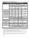
Bottom Heat Shield
Door Handle Holder
Leg Bolt and Washer
ST564
Fig. 21 Handle holder and heat shield positions.
ST536
Fig. 19 Attach the griddle handle.
ST536
Attach
griddle handle
11/00
Bushings
Spacer
Knob
Washer
Bolt
Storing the Handle
Use the removable handle to open or close the doors.
After using it, remove the handle so it will not get hot.
Store the handle in the handle holder installed behind
the right front leg. (Fig. 21)
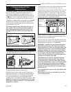
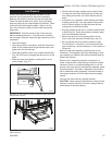
Install the Bottom Heat Shield
NOTE: The Bottom Heat Shield is required in most
installations. Refer to Floor Protection, Page 10, for
further details.
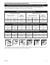
1. Loosen the four 10-24 x 1/2” hex head bolts from the
corners of the ash drop on the stove bottom.
3. Align the bottom heat shield holes with the four
bolts. The outside air cutout hole should be toward
the rear of the stove.
4. Tighten the four hex head bolts securely after pass-
ing all four bolts through the large end of the key-
holes and then pulling the shield forward to engage
the smaller ends of the keyhole slots. (Fig. 22)
ST857
Fig. 22 Attach the optional bottom heat shield.
Bottom Heat Shield
5. Attach the right side of the heat shield to the handle
holder using a #10 1/2” phillips sheet metal screw.