


19
Encore 1450 Non-Catalytic Woodburning Stove
30002425
Set Up Your Stove
Cast iron stoves are heavy, and it will take two to four
people to move your Encore into position.
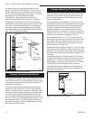
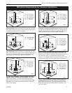
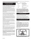
Wipe the protective
coating of oil from
the griddle with a
clean dry rag or a
paper towel.
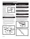
Install the handle
on the griddle.
First, place the
griddle upside
down at the edge
of a flat surface and
assemble the handle as shown.
With the handle pointing 45° from its final position,
tighten the nut as far as possible with the pliers. Move
the handle to its final position while still holding the nut
with the pliers.
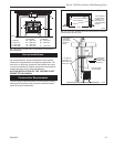
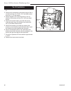
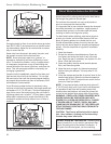
Install the Bottom Heat Shield
NOTE: The Bottom Heat Shield is required in most in-
stallations. Refer to Floor Protection, Page 9, for further
details.
1. Remove the four 10-24 x 1/2” hex head bolts from
the corners of the ash drop on the stove bottom.
2. Align the bottom heat shield against the spacers with
the outside air knockout hole toward the rear of the
stove.
3. Secure the shield with the four (4) hex head bolts
removed from the stove bottom previously.
4. Tighten securely.
Assembly
Adjust the Leg Levellers
Lift the stove slightly so there is no weight on the leg
while making the adjustment.
Reverse the Flue Collar (If Necessary)
Reverse the flue collar by removing the two (2) screws
that attach it to the back of the stove. Be sure the gas-
ket around the flue collar opening is in position when
you screw the collar back onto the stove.
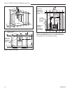
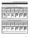
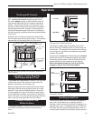
Attach the Primary Air Thermostat Handle
The primary air thermostat handle is the smaller of the
two black handles. Secure the handle to the stub on
the right side of the stove with an 8-32 x 2” slot head
machine screw.
Attach the Damper Handle
Use the 1/4” -20 x 3” screw to attach the damper handle
to the damper stub on the left side.
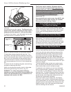
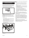
Assemble the Removable Insert Handle
The white removable insert handle opens and closes
the front doors. Remove after each use so it won’t get
hot. Store it in the handle holder installed behind the
right front leg. Assemble the handle by passing the 3³⁄₈"
screw through the ceramic shaft and into the bright
metal nub. Tighten carefully until snug.
ST516
Attach
gr
iddle handle
11/17/00 djt
ST516
Fig. 28 Attach the griddle handle.
ST540
Assembly
handle
11/00
ST540
Fig. 31 Assemble the front door handle.
ST635
Encore
Install thermostat
handle
2/01
ST635
Fig. 30 Attach thermostat handle.
ST853
Fig. 29 Use four (4) bolts to attach the bottom heat shield.
Rear
Bottom Heat
Shield
Bolts