


17
Encore 1450 Non-Catalytic Woodburning Stove
30002425
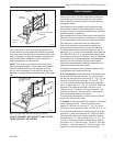
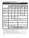
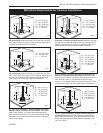
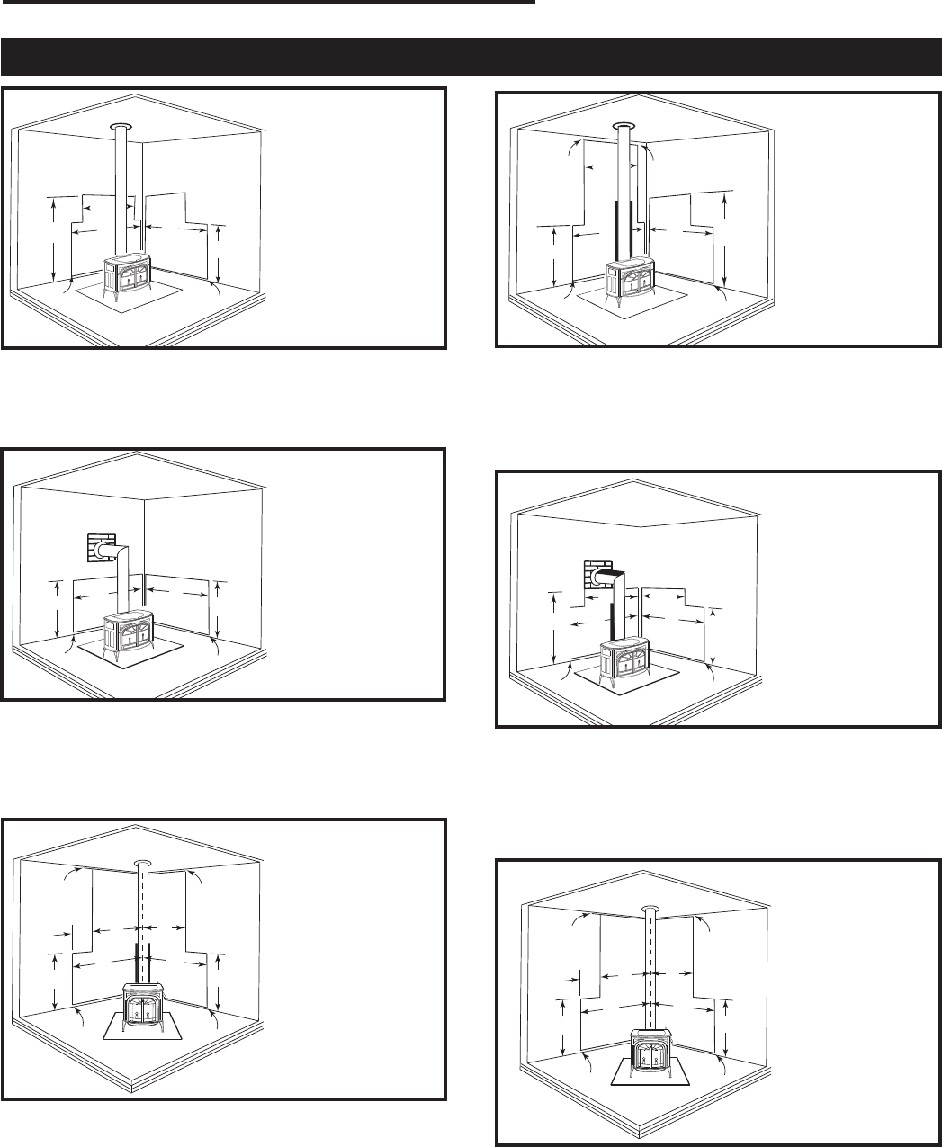
Wall Shield Requirements for Common Installations
E
E
C
B
A
B
D
ST629a
Encore
wall shield AA
02/01
E
E
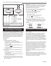
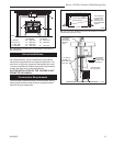
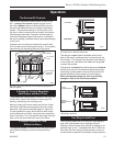
A = 30” (762 mm)
B = 44” (1118 mm)
C = 36” (910 mm)
D = 66” (1676 mm)
E = 1” (25 mm)
ST629a
Fig. 23 Parallel installation, vertical chimney connector,
with stove, connector and wall shields. Maximum reduction
for both rear and side wall. Wall shields may meet at corner if
desired. A heat shield 24” (610mm) in diameter suspended 1”
(25mm) below the ceiling must surround the chimney.
A
B
C
B
A
C
ST630
Enc
Wall shield
B
02/01
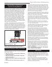
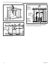
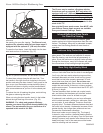
A = 48” (1219 mm)
B = 36” (910 mm)
C = 1” (25 mm)
ST630
Fig. 24 Parallel installation with rear wall pass-through,
two wall shields. Reduced clearances to both rear and side
walls. Wall shields may meet at corner if desired. Shielding for
connector is centered behind connector. Wall pass-through
must comply with codes. (See “Special Installations”)
B
C
D
A
C
ST630a
Encore
Wall shield
BB
02/01
E
F
F
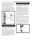
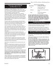
A = 30” (762 mm)
B = 23” (584 mm)
C = 44” (1118 mm)
D = 66” (1676 mm)
E = 36” (910 mm)
F = 1” (25 mm)
ST630a
Fig. 25 Parallel installation with rear wall pass-through
with stove, connector and wall shields. Wall shields may
meet at corner if desired. Connector shield extends 36” (914
mm) above flue collar, or to the elbow whichever is less.
Height “D” must be 66” (1676mm) or reach the thimble. Pass-
through must comply with codes. (See “Special Installations”.)
B
A
D
E
C
E
D
A
ST631
Encore
Wall shield
C
02/01
B
E
E
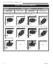
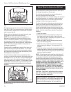
A = 29” (737 mm)
B = 45” (1143 mm)
C = 16” (406 mm)
D = 36” (910 mm)
E = 1” (25 mm)
ST631
Fig. 26 Corner installation, vertical chimney connector,
with rear, stove, connector and wall shields. Wall shields
MUST meet at corner. Connector heat shield extends 36”
(914 mm) above flue collar. A 24” (610 mm) diameter ceiling
heat shield must surround the chimney and be suspended 1”
(25 mm) from ceiling.
B
A
D
E
C
E
D
A
ST631a
Encore
Wall shield
CC
02/01
B
E
E
A = 29” (737 mm)
B = 45” (1143 mm)
C = 16” (406 mm)
D = 36” (910 mm)
E = 1” (25 mm)
ST631a
Fig. 27 Corner installation, vertical chimney connector,
two wall shields. Reduced side clearances. Wall shields
MUST meet at corner. A 24” (610 mm) diameter ceiling heat
shield must surround the chimney and be suspended 1” (25
mm) from ceiling.
E
E
C
B
A
B
D
ST629
Encore
wall shield
02/01
A = 30” (762 mm)
B = 48” (1219 mm)
C = 66” (1676 mm)
D = 36” (910 mm)
E = 1” (25 mm)
ST628
Fig. 22 Parallel installation, vertical chimney connector,
two wall shields. Reduced clearances for both rear and side
walls. Wall shields may meet at corner if desired. Shielding for
connector is centered behind connector.