


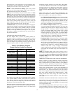
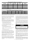
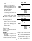
Table 1—Wiring Requirements
FROM
COMFORT ZONE
CENTER TO
NO.
OF WIRES
GAGE
MAX.
LENGTH
(FT)
Four Zone Controller
3‡ 18/22 200/100
5‡ 18/22 200/100
Remote Room Sen-
sors
2‡ 18/22 200/100
Remote Duct Sensors 2‡ 18/22 200/100
Dx Coil Sensor 2‡ 18/22 200/100
Home Access
Module
3‡ 18/22 1000/100
ISOSAT* 3‡ 18/22 1000/100
Transformer† 21875
* When using ISOSATS in interfacing multiple buses together, the length of
wiring between ISOSATS cannot exceed 4000 ft with 18 gage.
† 24 vac, 50-75 va
‡ Shielded cable recommended to reduce noise interference.
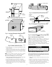
Step 3—Install Comfort Zone Center
NOTE: The Comfort Zone System is approved for indoor use
only and should never be installed with any of its components
exposed to the elements. The enclosure must be installed with
center cover to help prevent damage from other sources. Do not
mount Comfort Zone Center where it will be accessible to
children. Do not locate center in areas of the home that are noise
sensitive since relays are energized and de-energized during
operation and may be an annoyance. Install Comfort Zone in an
area with a temperature range between 32°F and 120° F.
Install Comfort Zone Center in either a vertical or horizontal
position. Locate in an area that is easily accessible in case
servicing should be required.
NOTE: Four vent plugs and 2 bushings have been supplied. Snap
bushings in the 1-in. diameter holes that are to be used for wiring
and place plugs in remaining holes.
To prevent possible damage to Comfort Zone Center, do not
mount on plenum, duct work, or flush against furnace.
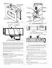
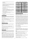
1. Separate Comfort Zone Center cover. (See Fig. 5)
2. Mount back plate of center cover to wall using screws and
wall anchors provided.
3. Level back plate and tighten screws.
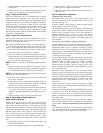
Step 4—Install Zone Dampers
IMPORTANT: If conditions exist for possible condensing, motor
must be positioned for adequate draining. (See Fig. 6.)
NOTE: If a multi-damper enabler is used to link dampers
together, add 5va per damper to the transformer power supply
rating. Reference multi-damper enabler Installation Instructions.
Zone dampers may be installed in any direction.
Install dampers so that actuator is visible for inspection and
accessible in the event it would ever need to be serviced. The black
mark on the end of damper shaft represents the position of damper
blade.
NOTE: Insulate damper using 1-1/2 in. insulation (check local
codes). In areas where excessive condensing may occur, carefully
insulate over the actuator assembly. Make sure insulation does not
interfere with operation of actuator.
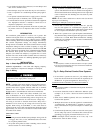
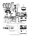
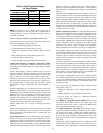
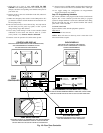
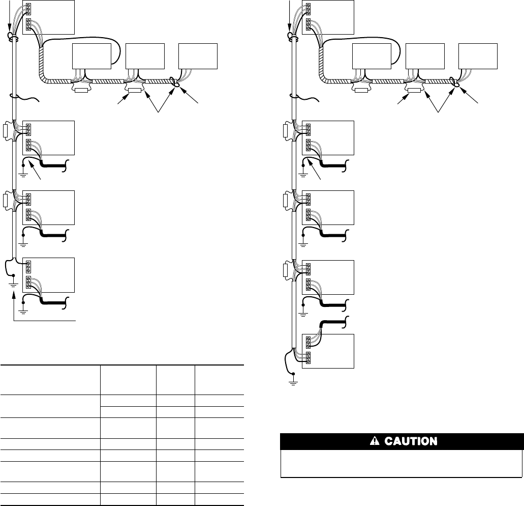
Fig. 3—Typical Communications Network
A93249
PORT #1
PORT #2
Comfort
Zone
I/O
Comfort
Zone
I/O
Comfort
Zone
I/O
SHIELD DRAIN WIRE (TYP)
NOTE 2NOTE 1
PORT #1
PORT #2
PORT #1
PORT #2
PORT #1
PORT #2
SHIELD DRAIN WIRE (TYP)
DEVICE BUS (TYP)
ISOSAT-01
ISOSAT-01
ISOSAT-01
ISOSAT BUS
BUILDING GROUND
NOTES:
1.Use butt splices, or solder,
for shield connections. Then
tape up shield.
2.Do not connect the shield
drain wire at the end of
Communication Bus. Cut
and tape up to avoid shorting.
NOTE 2
ISOSAT-01
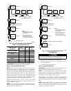
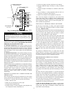
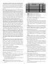
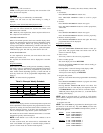
Fig. 4—Communication Network With
An ISOSAT-02
A93250
PORT #1
PORT #2
Comfort
Zone
I/O
Comfort
Zone
I/O
Comfort
Zone
I/O
SHIELD DRAIN WIRE (TYP)
NOTE 2NOTE 1
PORT #1
PORT #2
PORT #1
PORT #2
PORT #1
PORT #2
SHIELD DRAIN WIRE (TYP)
DEVICE BUS (TYP)
ISOSAT-01
ISOSAT-01
ISOSAT-02
ISOSAT BUS
BUILDING GROUND
NOTES:
1.Use butt splices, or solder,
for shield connections. Then
tape up shield.
2.Do not connect the shield
drain wire at the end of
Communication Bus. Cut
and tape up to avoid shorting.
NOTE 2
ISOSAT-01
TO PERSONAL COMPUTER OR MODEM
PORT #1
PORT #2
ISOSAT-01
3