


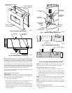
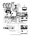
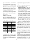
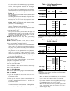
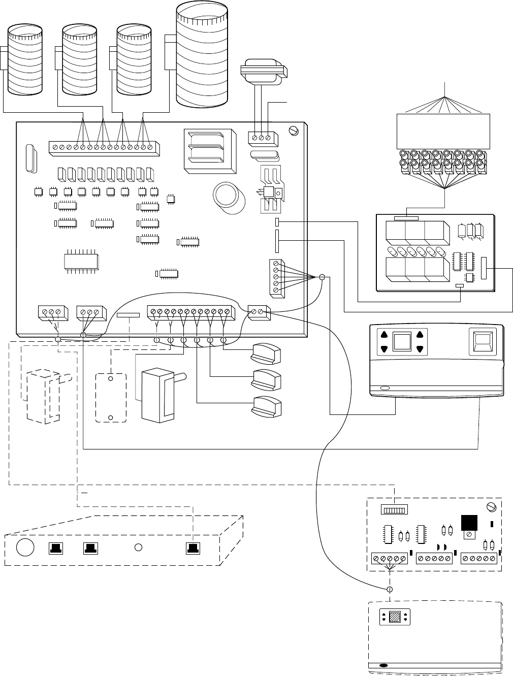
Fig. 16—Comfort Zone System Wiring Diagram
A94311
Zone Dampers
Dx Coil
Sensor
(optional)
Outside Air
Sensor
(optional)
Duct
Sensor
Zone 2*
Zone 3*
Zone 4*
Zone 1
4-Zone Controller
Remote Room
Sensors
72
68
2:45
24 VAC Transformer
(Field Supplied)
50 VAC req. for basic
4 damper system. Please
see Page 1, Electrical
Rating for details.
#16 AWG to
Grounded to Water Pipe
or Solid Electrical Ground
To
HVAC
System
UNIT 24 VAC (R)
COOL 1 (Y1)
COOL 2 (Y2)
HEAT 1 (W1)
HEAT 2 (W2)
FAN (G)
RV COOL (0)
OR
RV HEAT (B)
Power
CHR-06
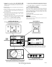
Communication Bus
COMFORT ZONE I/O
R
G
WR
G
COMM BUS
CONTROLLER
COMM
BUS HAM
R
W
R
W
R
W
R
W
R
W
R
W
OAT
LAT
ZT4
ZT3
ZT2
SHIELD
GROUND
WG
B
Y
R
SYSTEM CONTROLLER
CHR06
RELAY
CHR06
PWR
PWR. 24VAC
CL OP COM CL OP COM CL OP COM CL OP COM CL OP COM
BYPASS
ZN4
ZN3 ZN2 ZN1
* It is recommended that a 5 wire cable be used to install
Remote Room Sensors to allow
for future upgrade to Smart Sensors.
DX
W
B Y G W RB Y G W RB Y G W R
CALLOUT TO PHONE COMM BUSPOWER PHONE LINE
Custom Cable
Home Access Module
(optional)
Smart Sensor Power Pack
(optional)
Smart Sensor
(optional)
7