


2. Secure flexible duct to zone damper using SMACNA or other
approved method.
3. Properly seal joint using duct tape, mastic, or other approved
method. Do not allow mastic to come in contact with actuator.
4. Insulate damper using 1-1/2-in. to 2-in. insulation. (Check
your local codes.)
NOTE: All zone dampers and duct work must be properly
supported according to local codes or SMACNA standards.
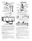
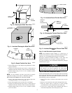
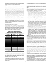
RECTANGULAR FIBROUS GLASS DUCT WORK
1. Insert 1 end of zone damper into 1 end of fibrous glass duct
work approximately 2- to 3-in. (See Fig. 14.)
2. Screw field-supplied screws and tabs into zone damper.
3. Properly seal joint using duct tape, mastic, or other approved
method. Do not allow mastic to come in contact with actuator.
4. Insulate damper using 1-1/2-in. to 2-in. insulation. (Check
your local codes.)
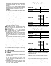
Step 5—Install Barometric Bypass Damper
NOTE: The barometric bypass damper is a critical part of
Comfort Zone System for control of minimum airflow and noise
reduction. It is recommended that the bypass be installed.
The bypass should be installed according to local codes and
SMACNA standards. Be sure bypass is properly supported.
For proper installation, refer to Installation Instructions packaged
with barometric bypass.
Failure to properly install bypass damper can cause perma-
nent damage to the HVAC equipment. For single speed
furnace applications bypass air must never exceed 25 percent.
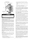
Step 6—Install Duct Temperature Sensor
Locate duct temperature sensor in main supply trunk after heating
and cooling coil and before bypass damper and first branch. The
duct temperature sensor must be radiant shielded to prevent heat
from affecting correct air temperature.
1. Drill a 7/8-in. hole at location in unit where sensor will be
installed.
2. Remove cover and insert sensor probe through 7/8-in. hole.
3. Drill two 1/16-in. holes to accept No. 6 screws through
pre-drilled holes in duct temperature sensor back plate.
4. Use two No. 6 sheet metal screws included with sensor to
mount duct temperature sensor back plate to unit.
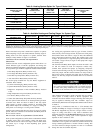
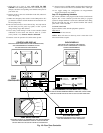
Fig. 10—Rectangular Metal Duct Work
A92478
DRIVE
ZONE
DAMPER
S-LOCK
SUPPLY
AIR DUCT
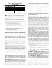
Fig. 11—Insulated Rectangular Metal Duct Work
A95131
1 / " TO 2"
INSULATION
1
2
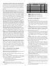
Fig 12—Round Flexible Duct Work
A95132
FLEXIBLE
DUCT
ZONE
DAMPER
Fig. 13—Insulated Round Flexible Duct Work
A95133
/ ″ STEEL STRAP
1
2
Fig. 14—Rectangular Fibrous Glass Duct Work
A92480
ZONE
DAMPER
2″ TO 3″
FIBROUS
GLASS
DUCTWORK
FIELD
SUPPLIED
SCREWS
Fig. 15—Insulated Rectangular Fibrous Glass Duct
Work
A95134
1 / ″ TO 2″
INSULATION
1
2
5