


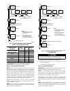
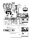
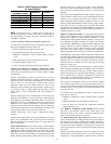
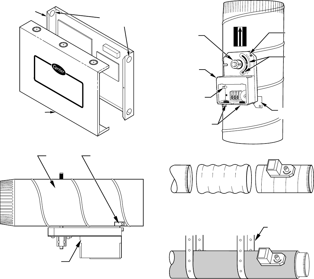
Before insulating the duct work, check for proper damper opera-
tion. Apply the 24vac between COM and OPN to open the damper
and COM and CLS to close the damper. (See Fig. 7.) The damper
will modulate counter-clockwise to open and clockwise to close.
If in an emergency it becomes necessary to force a damper open,
manually press in the red quick blade release button with one hand
and turn the mounting hub to reposition the damper shaft. Release
the button to hold the damper shaft in the new position.
To avoid noise and vibration, do not hard mount dampers to any
solid structure such as joists.
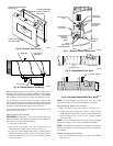
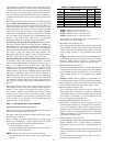
ROUND METAL DUCT WORK
IMPORTANT: If application exists with all metal duct work
without insulation, flex connectors must be used on each end of
zone dampers to avoid noise and vibration.
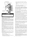
1. Crimp end of branch duct.
2. Slip end of zone damper over end of duct work. Use
self-tapping sheet metal screw to secure. (See Fig. 8.)
3. Properly seal joint using duct tape, mastic, or other approved
method. Do not allow mastic to come in contact with actuator.
4. Insulate damper using 1-1/2-in. to 2-in. insulation. (Check
your local codes.)
NOTE: All zone dampers and duct work must be properly
supported according to local codes or SMACNA standards.
RECTANGULAR METAL DUCT WORK
1. Make connections using S-lock and drives. (See Fig. 10.)
2. Properly seal joint using duct tape, mastic, or other approved
method. Do not allow mastic to come in contact with actuator.
3. Insulate damper using 1-1/2-in. to 2-in. insulation. (Check
your local codes.)
NOTE: All zone dampers and duct work must be properly
supported according to local codes or SMACNA standards.
NOTE: There should be a minimum of 4 ft between zone damper
and first branch duct if more than 1 branch duct is downstream of
zone damper.
ROUND FLEXIBLE DUCT WORK
1. Slip 1 end of flexible duct work over 1 end of zone damper.
(See Fig. 12.)
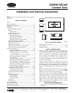
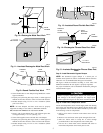
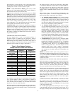
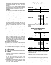
Fig. 5—Comfort Zone Center
A93247
Comfort Zone
Center
INTERCHANGEABLE
HOLE PLUGS AND
BUSHINGS
COMFORT ZONE CENTER
BACK PLATE
COMFORT ZONE
CENTER COVER
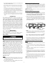
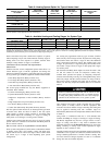
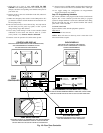
Fig. 6—Damper Motor Positioning
A95128
DAMPER MOUNTING
BRACKET
ACTUATOR
Fig. 7—Damper 24-vac Connections
A95096
90
45
0
CLS
COM
OPN
ACTUATOR
HOUSING
MOUNTING
BRACKET
QUICK BLADE
RELEASE
BUTTON
(RED)
FIELD
INSTALLED
POWER WIRING
ANGULAR
ROTATION
STOPS
POSITION
INDICATOR
MOUNTING
HUB
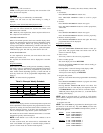
AIRFLOW
AIRFLOW
Fig. 8—Round Metal Duct Work
A95129
SUPPLY
FLEX
CONNECTOR
ZONE DAMPER
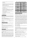
Fig. 9—Insulated Round Metal Duct Work
A95130
/ ″ STEEL STRAP
1
2
4