


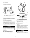
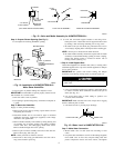

Step 3—Prepare Plenum Opening (See Fig. 2.)
1. Use template for marking humidifier opening.
2. Tape in place on plenum making sure template is level.
IMPORTANT: For humidifier to operate properly it must be level
and mounted on a vertical surface.
3. Drill four 1/8-in. holes in plenum.
4. Cut opening in plenum using heavy solid lines on template as
a guide.
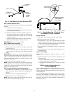
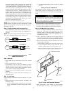
Step 4—Mount the Humidifier
Supply or return plenum mounting:
1. Remove unit access door by turning 2 pawl latches 1/2 turn
and pulling door forward.
2. Determine whether unit is to be used for right- or left-hand
installation and apply gasket tape (supplied) to unit flange
intended to seat against duct.
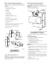
3. Remove media assembly from cabinet by lifting bearing end
of assembly out of bearing retainer and pulling assembly
toward outlet duct, thus disengaging media from motor.
Remove media through unit access opening.
4. Remove pin from float assembly and remove float and arm.
Remove drain plug and water pan.
NOTE: Water pan must be tilted for removal.
5. Mount unit to duct using pre-drilled holes and four 1/2-in.
long screws found in parts bag.
6. Level unit and attach support bracket to unit using 1/4-in.
blunt point screw. Attach other end of support bracket to duct
by drilling a hole and using remaining 1/4-in. long screw.
7. Re-install water pan and drain plug. Re-attach float arm to
valve body by aligning holes in both parts and re-inserting pin.
NOTE: Pin may be re-inserted from either direction.
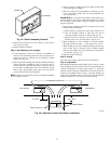
8. Re-install media assembly. Ensure that square shaft of media
assembly is located inside mating opening of motor coupling.
Ensure that bearing washer is located on interior side of
bearing retainer. (See Fig. 15.)
Step 5—Install Bypass Duct
Attach field-supplied 6-in. diameter duct, elbow, or starting collar
with field-supplied 1/4-in. zip screws. Install supplied 6-in. damper
in 6-in. duct connector.
IMPORTANT: On systems with central cooling, the damper
should be closed during cooling season to prevent bypass air.
Do not support weight of duct from humidifier — damage
could result.
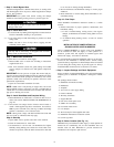
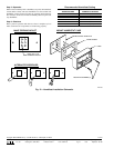
Step 6—Install Drain Line
1. Use 1/2-in. ID field-supplied vinyl tubing or equivalent tubing
to connect overflow drain connection on unit water pan to
drain. (See Fig. 16.)
2. Use worm drain clamp to hold tubing in position over
overflow drain connection.
IMPORTANT: Make sure that line is free of traps due to sagging
and has sufficient pitch to drain.
3. Unit must be level to provide proper drainage.
Step 7—Make Water Connection
1. Mount saddle valve on cold water line according to local
codes.
2. For plastic tube installations: run 1/4-in. OD tubing (supplied)
from saddle valve to float valve. Prepare tubing ends with
plastic compression sleeves and brass inserts, and tighten
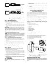
→ Fig. 15—Valve and Media Assembly for HUMCCWTR2019-A--
A98370
PIN
FLOAT
ARM
GASKET
RETAINER
BEARING
VALVE SEAT
SUPPORT
BRACKET
(LEFT HAND INSTALLATION SHOWN) FLOAT VALVE ASSEMBLY REINSTALLING MEDIA ASSEMBLY
VALVE BODY
WASHER
1
⁄4 IN. BLUNT
POINT SCREW
1
⁄2 IN. LONG
SCREW
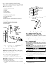
→ Fig. 14—Installation of HUMCCWTR2019-A--
Water Saver Humidifier
A98369
VERTICAL
HORIZONTAL
BYPASS UNITS
DRILL (2) HOLES
IN DUCT
FOR #8 SHEETMETAL
SCREWS
"N" COIL
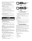
Fig. 16—Water Level in HUMCCWTR2019-A--
A96013
DRAIN PLUG
OVERFLOW TUBE
1
⁄4″
9
→
→