


Step 1—Inspect Package and Check Equipment
Inspect the contents of packaged humidifier. File claim with
shipping company prior to installation if shipment is damaged or
incomplete.
The package should contain:
1. Humidifier and media assembly
2. Humidistat
3. Template
4. 6-in. damper
5. Owner’s Manual
6. Warranty Certificate
7. Solenoid valve with bridge rectifier
8. Transfer tube
9. Saddle valve assembly with adapter
10. Three pair of miscellaneous screws
11. Six sheet metal screws
12. Foam tape
13. Water noise reducer (use for water pressure over 60 psi)
14. Worm clamp for field-supplied drain tube
15. Humidifier maintenance instruction sticker
16. Carrier logo label
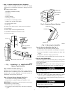
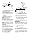
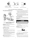
Step 2—Select Location (See Fig. 12.)
Humidifier may be installed on either supply or return plenum. If
furnace has air conditioning coil, be sure unit does not interfere
with coil ends. Remember to provide clearance for maintenance
and evaporator pad removal.
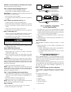
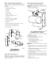
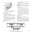
Step 3—Prepare Plenum Opening (See Fig. 2.)
1. Use template for marking humidifier opening.
2. Tape in place on plenum making sure template is level.
IMPORTANT: For humidifier to operate properly it must be level
and mounted on a vertical surface.
3. Drill four 1/8-in. holes in plenum.
4. Cut opening in plenum using heavy solid lines on template as
a guide.
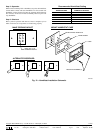
Step 4—Mount Humidifier
1. Attach foam tape on inside of mounting flange.
2. Determine discharge direction.
3. If right-hand discharge is required:
a. Remove side door and media pad assembly.
b. Invert unit 180 degrees.
c. Re-install media pad and door.
IMPORTANT: Always ensure pad assembly is in the upright
position.
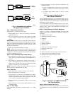
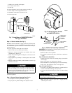
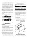
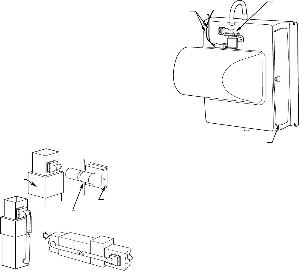
4. Attach solenoid valve to unit housing using two screws in
upper mounting holes. (See Fig. 13.) Do not over tighten
screws.
5. Attach transfer tube to solenoid valve and insert free end into
inlet fitting on top of unit housing.
6. Attach bridge rectifier to solenoid valve.
7. Insert sheet metal screws into lower holes in plenum, pre-
drilled using template.
8. Tighten screws until heads protrude approximately 3/16-in.
9. Hang humidifier on bottom screws and push top of humidifier
to plenum, aligning top screw holes with flange, and insert
screws.
10. Align and level unit.
11. Tighten all screws for air tight seal.
→ Fig. 12—Installation of
HUMCCSBP2017-A--
Bypass-Type Humidifier
A98367
VERTICAL
HORIZONTAL
BYPASS UNITS
DRILL (2) HOLES
IN DUCT
FOR #8 SHEETMETAL
SCREWS
"N" COIL
ACCESS
DOOR
→ Fig. 13—Mounting Solenoid Valve
on HUMCCSBP2017-A-- Humidifier
A98368
SOLENOID
VALVE
ASSEMBLY
PAD
ACCESS
DOOR
BROWN
7
→