


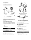
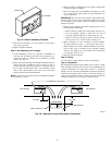

Step 5—Install Bypass Duct
Attach field-supplied 6-in. diameter duct, elbow, or starting collar
with field-supplied 1/4-in. zip screws. Install supplied 6-in. damper
in 6-in. duct connector.
IMPORTANT: On systems with central cooling, the damper
should be closed during cooling season to prevent bypass air.
Do not support weight of bypass duct from humidifier —
damage could result.
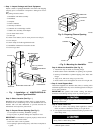
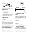
Step 6—Install Drain Line
1. Use 5/8-in. ID vinyl tubing (field supplied) to connect drain on
bottom of humidifier housing to an open drain.
2. Use worm clamp to hold drain tubing in position over drain
fitting outlet.
3. Make sure line is free of traps due to sagging and has
sufficient pitch to drain.
Unit may leak if drain tubing is misapplied. Do not insert
tubing inside of drain fitting outlet.
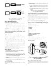
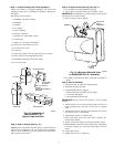
Step 7—Make Water Connection
If garden hose is not used for water supply:
1. Mount saddle valve on water line according to instructions
supplied with valve.
2. Run 1/4-in. diameter (water line grade) tubing from saddle
valve to adapter on solenoid valve and tighten compression
fittings.
IMPORTANT: If water pressure is higher than normal (60 psi),
use noise suppression disk included in parts bag. (Read water noise
reducer note located inside package for instructions). For normal
operation, saddle valve need only be opened 1 full turn to meet
performance requirements.
3. Open valve and check installation for leaks.
NOTE: Saddle valve is self piercing on copper lines; 1/4-in. hole
must be drilled in steel or iron pipes. Use only a grounded drill or
a hand drill to avoid shock hazard. Turn off water and drain the
pipe prior to drilling 1/4-in. hole.
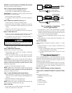
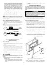
Step 8—Install Humidistat and Complete Wiring
1. Mount humidistat on inside wall, or return-air duct in accor-
dance with section INSTALLATION OF HUMIDISTAT on
page 10.
2. Wire brown low-voltage leads to furnace control board, or
install a field-supplied step-down transformer 115vac/24vac
60Hz to power solenoid valve. (See Fig. 4.) Make sure bridge
rectifier is attached to coil of solenoid valve.
NOTE: Wiring must comply with National Electrical Code and
any local codes or ordinances that may apply.
Step 9—Start-Up
1. Open saddle valve to permit water flow to the solenoid.
2. Check all connections for water leaks.
3. Set thermostat to call for heat. Set humidistat for highest
humidity setting making sure contacts are closed. After a few
minutes of operation, check the drain connection for leaks and
to see if water is flowing through humidifier.
4. Reverse thermostat and humidistat settings to insure proper
shutdown.
5. Reset thermostat to normal setting. Reset humidistat to rec-
ommended setting.
Step 10—Final Steps
Attach humidifier maintenance instruction sticker to a visible
location.
1. Inform homeowner of proper operation, maintenance, and
humidistat setting.
a. If unit is installed during cooling season, close bypass
damper, set humidistat for summer setting (OFF or lowest
setting).
b. If installed during heating season, set unit for normal
operation.
INSTALLATION OF HUMCCWTR2019-A--
BYPASS WATER SAVER HUMIDIFIER
Carrier’s HUMCCWTR2019-A-- bypass water saver humidifier
can be installed on either the supply or return plenum of a
forced-air system. This unit requires an external bypass duct
between the supply- and return-air ductwork.
It is recommended to install the humidifier where it can be easily
serviced. If this humidifier is installed with a central cooling
system the factory-supplied 6-in. shutoff damper must be installed
to close during the cooling season to prevent bypass air. Always
install humidifier downstream of an electronic air cleaner.
Step 1—Inspect Package and Check Equipment
Inspect contents of packaged humidifier. File claim with shipping
company prior to installation if shipment is damaged or incom-
plete.
The package should contain:
1. Humidifier and media assembly
2. Humidistat
3. Template
4. Ten ft 1/4-in. water supply tubing
5. Owner’s Manual
6. Warranty Certificate
7. Support Bracket
8. One 1/4-in. blunt point screw
9. Saddle valve assembly
10. Four sheet metal screws
11. 6-in. damper
12. Worm clamp for field-supplied drain tube
13. Humidifier maintenance instruction sticker
14. Carrier logo label
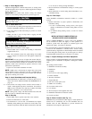
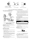
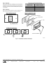
Step 2—Select Location (See Fig. 14.)
Humidifier may be installed on either supply or return plenum. If
furnace has air conditioning coil, be sure humidifier does not
interfere with coil ends. Remember to provide clearance for
maintenance and evaporator pad removal.
8
→
→
→
→
→