


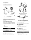
compression fittings. Plastic compression nut supplied with
float valve should not be torqued greater than 25 in.-lb. For
copper tubing installations: copper tubing may be connected to
float valve by using a field-supplied 1/4 to 1/4 in. straight-
through compression union. Run copper tubing to 1 side of
compression union and use a standard compression sleeve.
Tighten compression nut to torque recommended by manu-
facturer. Attach approximately 6 in. of polyethylene supply
tubing (supplied) between compression union and float valve.
Prepare polyethylene tubing on both ends with brass inserts to
prevent tubing collapse. Use compression nut at union to
manufacturer’s recommended torque, tighten plastic nut on
float valve to maximum of 25 in.-lb.
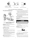
3. Open valve and check installation for leaks.
NOTE: Valve is self piercing on copper lines; 1/4-in. hole must
be drilled in steel or iron pipes. Use only a grounded drill or a hand
drill to avoid shock hazard. Turn off water and drain the pipe prior
to drilling 1/4-in. hole.
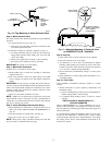
Step 8—Install Humidistat and Complete Wiring
1. Mount humidistat on inside wall or return-air duct in accor-
dance with section INSTALLATION OF HUMIDISTAT on
page 10.
NOTE: Wiring must comply with national electrical code and any
local codes or ordinances that may apply. (See Fig. 17.)
Step 9—Start-Up
1. Open saddle valve to permit water to flow to the solenoid
valve.
2. Check all connections for water leaks.
3. Set thermostat to call for heat. Set humidistat at highest
humidity setting to be sure the contacts are closed. After a few
minutes of operation, check the drain connection for leaks and
to see if water is flowing through humidifier.
4. Reverse thermostat and humidistat settings to insure proper
shutdown.
5. Reset thermostat to normal setting. Reset humidistat to rec-
ommended setting.
Step 10—Final Steps
Attach humidifier maintenance instruction sticker to a visible
location.
1. Inform homeowner of proper operation, maintenance, and
humidistat setting.
a. If unit is installed during cooling season, close bypass
damper, set humidistat for summer setting (OFF or lowest
setting).
b. If installed during heating season, set unit for normal
operation.
INSTALLATION OF HUMIDISTAT
The humidistat provides automatic control of humidifiers in
central heating systems. It is designed for low voltage, wall, or
surface duct mounting and contains a SPST snap-acting dustproof
switch.
Disconnect power supply before making wiring connections
to prevent possible electrical shock and equipment damage.
Make wiring connections in accordance with Installation
Instruction supplied with the humidifier.
1. Installer must be a trained, experienced service person.
2. Disconnect power supply before beginning installation.
3. Conduct a thorough checkout before leaving installation.
Step 1—Wall Mounting (Low Voltage)
1. Choose a location for humidistat about 5 ft above floor on
inside wall with average room temperature and relative
humidity conditions. Maximum ambient temperature of se-
lected location must not exceed 125°F. Humidistat may be
mounted directly on wall.
2. Drill a small hole in wall and run low-voltage wiring to
location chosen. Pull about 6 in. of wire through hole. Plug
opening to prevent drafts from affecting humidistat operation.
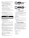
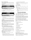
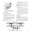
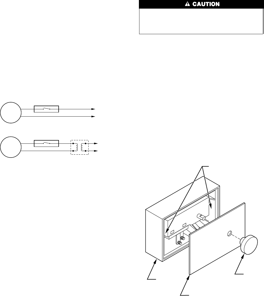
3. Remove knob, faceplate, and switch assembly from case by
following steps listed below.
a. Remove knob by pulling away from casing. (See Fig. 18.)
b. Lift off faceplate, starting at right side. Left end of
faceplate protrudes under lip of casing. (See Fig. 18.)
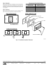
c. Remove switch by removing 2 screws in back of casing.
Pressing tab on case. Lift out control. (See Fig. 19.)
4. Make connections to screw terminals on switch assembly.
Re-install switch into casing — secure with 2 short screws.
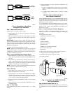
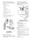
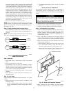
Fig.17—Humidistat Installation for
HUMCCWTR2019-A--
A96014
MOTOR
HUMIDISTAT
115V
FIELD
WIRING
TRANSFORMER
(10-VA)
24V
MOTOR
HUMIDISTAT
24VAC
FURNACE
Fig. 18—Knob and Faceplate Removal
A97102
KNOB
FACEPLATE
MOUNTING HOLES
CASE
10