


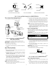
5. Mount case horizontally over wires directly to wall using 2
long screws provided.
6. Replace faceplate and knob.
Step 2—Duct Mounting (Low Voltage)
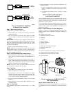
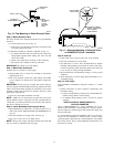
1. Locate humidistat at least 8 in. upstream of humidifier in
return-air duct. If mounting near elbow area, keep device 6 in.
upstream of elbow so element will be affected by normal
airflow. (See Fig. 20.)
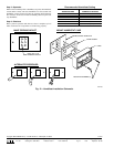
2. Remove protective backing from template furnished with each
control and apply self-adhesive side on return air duct at
selected location. Following instructions on template and in
Fig. 21, drill 2 mounting holes and six 1/4-in. diameter sensing
holes in duct. Sensing holes allow return air to reach nylon
sensing element and operate humidistat.
NOTE: If desired, cut square hole in duct as indicated on template
as an alternative to holes.
3. Remove protective backing from foam gasket provided with
control and apply to template.
4. Run low-voltage wire from humidifier to template. Lay wire
over 1 side of foam gasket. Wire can enter humidistat case
from any direction.
IMPORTANT: Do not position wire directly under standoff pro-
jections at back of case. If wire is under these projections, case will
not seat tightly against gasket causing air leakage and possible
improper operation.
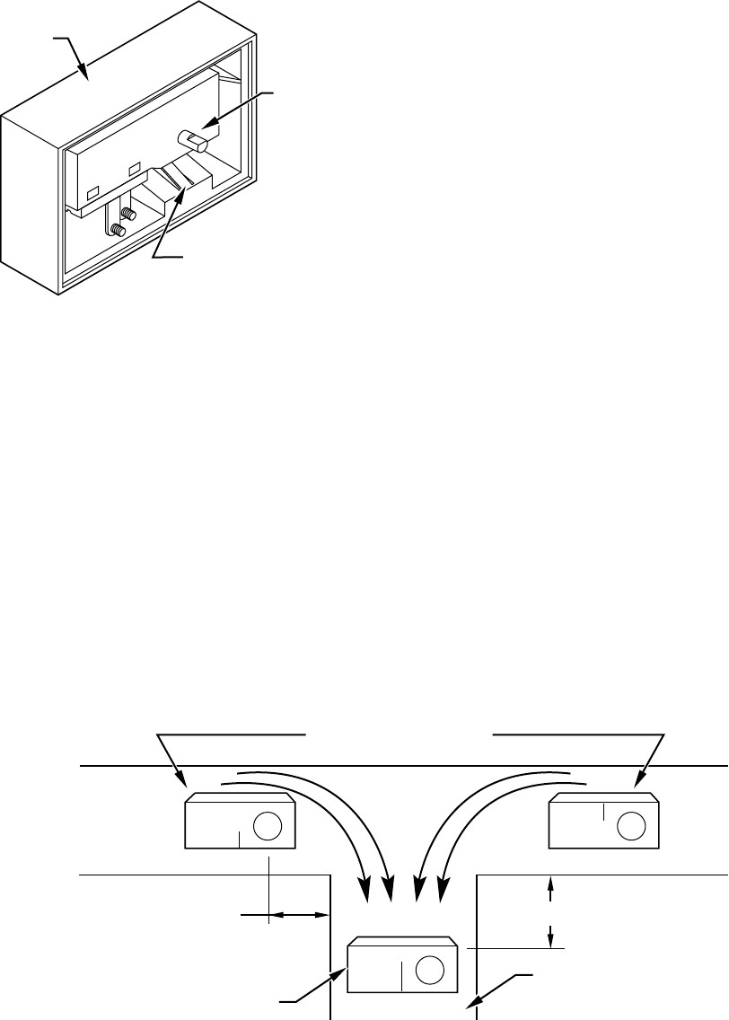
5. Remove knob, faceplate, and switch assembly from case by
following steps listed below.
a. Remove knob by pulling away from casing. (See Fig. 18.)
b. Lift off faceplate, starting at right side. Left end of
faceplate protrudes under lip on casing. (See Fig. 18.)
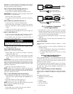
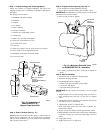
c. Remove switch by removing 2 screws in back of casing.
Pressing tab on case. Lift out control. (See Fig. 19.)
6. Make connections to screw terminals on switch assembly.
Re-install switch into casing — secure with 2 short screws.
7. While holding wire in place. Mount humidistat case horizon-
tally on duct using 2 mounting screws provided. Tighten
firmly so that gasket seals space around wires and between
case and duct. (See Fig. 21.)
8. Replace faceplate and knob.
Step 3—Wiring
All wiring must comply with local codes and ordinances.
Step 4—Adjustment
Recommended humidistat setting should only be used as a guide.
After adjustment of setting, allow at least 5 hr for equilibrium to be
reached. Condensation on single pane windows or woodwork
indicates excessive moisture. Condensation must not be allowed to
continue for extended periods of time, or moisture damage can
result. Lower humidistat setting in small steps until condensation
disappears. However, if air is too dry, raise the setting.
Fig. 20—Alternate Location Duct Mount Installation
A97104
ALTERNATE LOCATIONS
BEST LOCATION
RETURN AIR DUCT
5 IN. MIN. 15 IN. MIN.
RETURN AIR RETURN AIR
Fig. 19—Switch Assembly Removal
A97103
CASING
TAB
CONTROL
11