


9
UNIT DAMAGE HAZARD
Failure to follow this caution may result in furnace
component damage.
DO NOT use wire brush or other sharp object to inspect or
dislodge materials in secondary heat exchangers as cutting
of the secondary heat exchanger protective coating may
occur. Flush with water only.
CAUTION
!
8. Flush inside of collector box with water until discharge
from condensate trap is clean and runs freely.
9. Inspect inside area of collector box for any pieces of
foreign materials and remove them if present.
10. Reassemble inducer assembly by reversing items 5--7.
Tighten the vent coupling clamp screw(s) to 15 in.--lb of
torque.
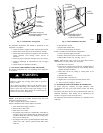
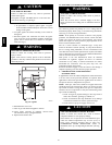
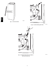
NOTE: If seal between the inducer housing and the collector
box is damaged in any way, it must be repaired. To repair, apply
sealant releasing agent such as PAM cooking spray or equivalent
(must not contain corn nor canola oil, halogenated hydrocarbons
nor aromatic content, to prevent inadequate seal from occurring)
to inducer housing. (See Fig. 12.) Apply a small bead of G.E.
RTV 162, G.E. RTV 6702, or Dow -- Corning RTV 738 sealant to
groove in collector box.
11. Refer to furnace wiring diagram and reconnect wires to
inducer motor and pressure switches or connectors.
12. Reconnect pressure tubes to pressure switches. See
diagram on main furnace door for proper location of tubes.
Be sure tubes are not kinked. (See Fig. 10.)
13. Turn on gas and electrical supplies to furnace.
14. Check furnace operation through two complete heat
operating cycles. Check area below inducer housing, vent
pipe, and condensate trap to ensure no condensate leaks
occur. If leaks are found, correct the problem.
15. Check for gas leaks.
16. Replace main furnace door.
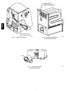
RTV
PAM
A93081
Fig. 12 -- Gasket on Collector Box
FIRE AND EXPLOSION HAZARD
Failure to follow this warning could result in personal
injury , death o r property damage.
Never test for gas leaks with an open flame. Use a
commercially available soap solution made s pecifically for
the d etection of leaks to check all connections.
!
WARNING
G. SERVICING HOT SURFACE IGNITER
BURN HAZARD
Failure to follow t his caution may result in personal injury.
Allow igniter to cool before removal. Normal operating
temperatures exceed 2000_.
CAUTION
!
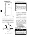
The igniter does NOT require annual inspection. Check igniter
resistance before removal.
1. Turn off gas and electrical supplies to furnace.
2. Remove main furnace door.
3. Disconnect igniter wire connection.
4. Check igniter resistance. Igniter resistance is affected by
temperature. Only check resistance when the i gniter is at
room temperature.
a. Using an ohm meter, check resistance across both igniter
leads in connector .
b. Cold reading should be between 40 ohms and 70 ohms.
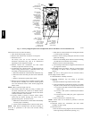
5. Remove igniter assembly.
a. Remove burner box cover.
b. Remove igniter wires from slot i n manifold grommet.
(See Fig. 7.)
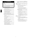
c. Using a 1/4-- in. driver, remove the single screw securing
theigniterbrackettotheburnerboxbracket(SeeFig.13.)
and carefully withdraw the igniter and bracket assembly
through the front of the burner box without striking the
igniteron surrounding parts.Notethatthe igniterbracket
has a handle that extends to the front of the burner box
to aid in handling. (See Fig. 13.)
d. Inspect igniter for signs of damage or failure.
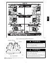
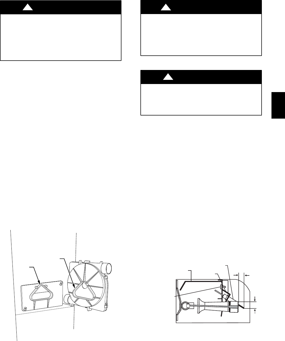
BRACKET
IGNITER
9/16˝
11/16˝
EXTENDED IGNITER
BRACKET HANDLE
IGNITER BRACKET
MOUNTING SCREW
A05075
Fig. 13 -- Igniter Bracket
58MVC