


5
ELECTRICAL SHOCK HAZARD
Failure to follow this warning could result in personal
injury or death.
Blower access panel door switch opens 115--v power to
furnace control. No component operation can occur.
Caution must be taken when manually closing this switch
for service purposes.
!
WARNING
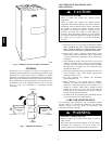
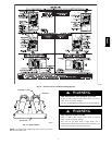
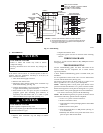
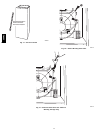
14. Turn on electrical supply. Manually close blower access
panel door switch. Use a piece of tape to hold switch
closed. Check for proper rotation and speed changes
between heating and cooling by jumpering R to G and R
to Y/Y2 on furnace control thermostat terminals. (See Fig.
15.)
15. If furnace is operating properly, release blower access
panel door switch, replace blower access panel, and
replace main furnace door.
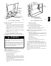
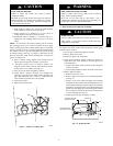
C. CLEANING BURNERS
The following items should be performed by a qualified service
technician. If the burners develop a n accumulation of light dirt or
dust, they may be cleaned by using the following procedure:
1. Turn off gas and electrical supplies to furnace.
2. Remove main furnace door.
3. Remove burner box cover.
4. Using backup wrench, disconnect gas supply pipe from
furnace gas control valve.
UNIT DAMAGE HAZARD
Failure to follow this caution may result in furnace
component damage.
Label all wires prior to disconnection when servicing
controls. Wiring errors can cause improper and dangerous
operation.
CAUTION
!
5. Remove wires from gas valve. Note location f or
reassembly.
6. Remove burner box pressure tube from gas valve regulator
fitting.
7. Unplug igniter from harness.
8. Remove igniter l eads from s lot in manifold grommet.
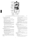
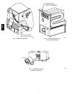
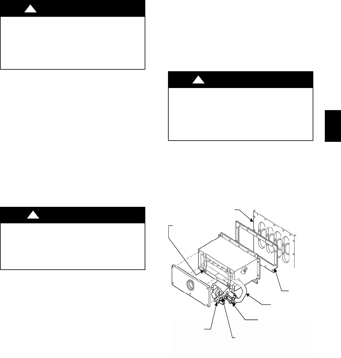
9. Remove screws that secure manifold to burner box. (See
Fig. 6.)
NOTE: Do not remove burner box from cell panel.
10. Remove manifold, orifices, and gas valve as 1 assembly.
11. Remove screws attaching burner assembly in burner box.
NOTE: Use care when removing and reinstalling burners not to
strike the hot surface igniter.
12. Remove burner assembly from burner box. NOTE: All
burners are attached to burner bracket and can be removed
as 1 assembly .
13. Clean burners with soft brush and vacuum.
14. Reinstall manifold, orifice, and gas valve assembly in
burner box. Ensure manifold seal grommet is installed
properly and burners fit over orifices.
15. Reinsert the igniter wires in the slot in the manifold
grommet, dressing the wires to ensure there is no tension
on the igniter itself. (See Fig. 7.)
ELECTRICAL SHOCK HAZARD
Failure to follow this warning could result in personal
injury or death.
Igniter wires must be securely placed in slot in manifold
grommet or else they could become pinched or severed and
electrically sh orted.
!
WARNING
16. Reconnect wires to gas valve and igniter. Refer to furnace
wiring diagram for proper wire location.
17. Reinstall burner box pressure tube to gas valve regulator
fitting.
18. Reinstall gas supply pipe to furnace gas control valve
using backup wrench on gas valve to prevent rotation and
improper orientation.
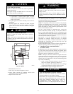
GAS
CONTROL
VALVE
THROTTLING
VALVE
MANIFOLD
GASKET
CELL
PANEL
MANIFOLD
MOUNTING
SCREWS
GAS VALVE
REGULATOR
FITTING
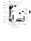
A07562
Fig. 6 -- Burner Box Assembly
58MVC