


8
19. Replace burner box cover.
20. Turn on gas and electrical supplies to furnace.
21. Check for gas leaks.
22. Replace main furnace door.
D. CLEANING HEAT EXCHANGERS
The following items should be performed by a qualified service
technician.
Primary Heat
Exchangers
If the heat exchangers get an accumulation of light dirt or dust on
the inside, they may be cleaned by the following procedure:
NOTE: If the heat exchangers get a heavy accumulation of soot
and carbon, both the primary and secondary heat exchangers
should be replaced rather than trying to clean them thoroughly
due to their intricate design. A build--up of soot and carbon
indicates that a problem exists which needs to be corrected, such
as improper adjustment of manifold pressure, insufficient or poor
quality combustion a ir, improper vent termination, incorrect size
or damaged manifold orifice(s), improper gas, or a restricted heat
exchanger (primary or secondary). Action must be taken to
correct the problem.
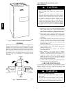
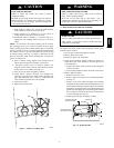
1. Turn off gas and electrical supplies to furnace.
2. Remove main furnace door.
UNIT DAMAGE HAZARD
Failure to follow this caution may result in furnace
component damage.
Label all wires prior to disconnection when servicing
controls. Wiring errors can cause improper and hazardous
operation.
CAUTION
!
3. Disconnect wires or connectors to flame rollout switch,
gas valve, igniter, and flame sensor.
4. Disconnect combustion --air intake pipe from intake
housing.
5. Remove the pressure switch tube fro m intake housing.
6. Remove screws attaching intake housing to burner box,
and rotate intake housing away from burner box for
removal.
7. Using backup wrench, disconnect gas supply pipe from
furnace gas control valve.
8. Disconnect pressure tubing from gas valve.
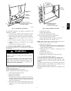
9. Remove two screws attaching top filler panel and rotate
upwards to gain access to screws attaching burner box to
cell panel.
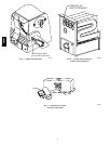
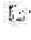
10. Remove screws attaching burner box to cell panel. (See
Fig. 6.)
NOTE: Burner box, cover, manifold, gas valve, and burner
assembly should be removed as one assembly.
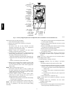
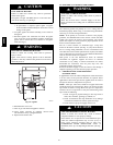
11. Clean heat exchanger openings with a vacuum and a soft
brush. (See Fig. 8.) NOTE: After cleaning, inspect the heat
exchangers to ensure they are free of all foreign objects
that may restrict flow of combustion products.
12. Reverse items 4 through 10 for reassembly.
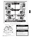
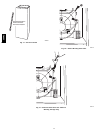
NOTE: Be sure burner box gasket is installed between burner
box and cell panel. ( See Fig. 6.) If gasket is damaged, replace it.
NOTE: Inspect combustion-- air intake housing. If foamed gasket
was removed, check for any damage. If gasket is damaged in any
way, it must be repaired. To repair, remove damaged gasket
section, apply sealant releasing agent such as PAM cooking spray
or equivalent (must not contain corn nor canola oil, halogenated
hydrocarbons nor aromatic content, to prevent inadequate seal
from occurring) to burner box and apply a small bead of G.E.
RTV 162, G.E. RTV 6702, or Dow -- Corning RTV 738 sealant to
edge of combustion--air intake housing. (See Fig. 9.)
UNIT MAY NOT OPERATE
Failure to follow this caution may result in improper unit
operation.
Failure to attach ground wire to an adequate casing ground
may cause the furnace control to lock out. The ground wire
from the gas valve MUST be attached to the burner box
attachment screw.
CAUTION
!
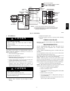
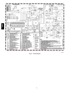
13. Refer to furnace wiring diagram and reconnect wires to
flame rollout switch, gas valve, igniter, and flame sensor.
14. Reconnect pressure switch tubes to gas valve and intake
housing. Refer to tube routing label on main furnace door
for proper tube location. (See Fig. 10.) Be sure tubes are
not kinked.
15. Turn on gas and electrical supplies to furnace.
16. Check furnace operation through 2 complete heat
operating cycles. Look through sight glass in burner
enclosure to check burners. Burner flames should be clear
blue, almost transparent. (See Fig. 11.)
17. Check for gas leaks.
FIRE OR EXPLOSION HAZARD
Failure to follow this warning could result in personal
injury, death, or property damage.
Never test for gas leaks with an open flame. Use a
commercially available soap solution made s pecifically for
the d etection of leaks to check all connections.
!
WARNING
18. Replace main furnace door.
E. Secondary Heat E xchangers
NOTE: The condensing side (inside) of the secondary heat
exchangers CANNOT be serviced or inspected. A small number
of bottom outlet openings can be inspected by removing the
inducer assembly. See Flushing Collector Box and Drainage
System section for details on removing inducer assembly.
F. FLUSHING COLLECTOR BOX AND DRAINAGE
SYSTEM
1. Turn off gas and electrical supplies to furnace.
2. Remove main furnace door.
3. Disconnect inducer motor and pressure switch wires or
connectors.
4. Disconnect pressure switch tubes.
5. Disconnect vent pipe from inducer housing outlet by
loosening c oupling clamp on inducer outlet.
6. Disconnect drain tube from inducer housing. (See Fig.
10.)
NOTE: Ensure the drain tube disconnected from the inducer
housing is higher than the collector box opening or water will
flow out of tube.
7. Remove inducer housing assembly by removing 4 bolts
attaching assembly to cell panel.
58MVC