


11
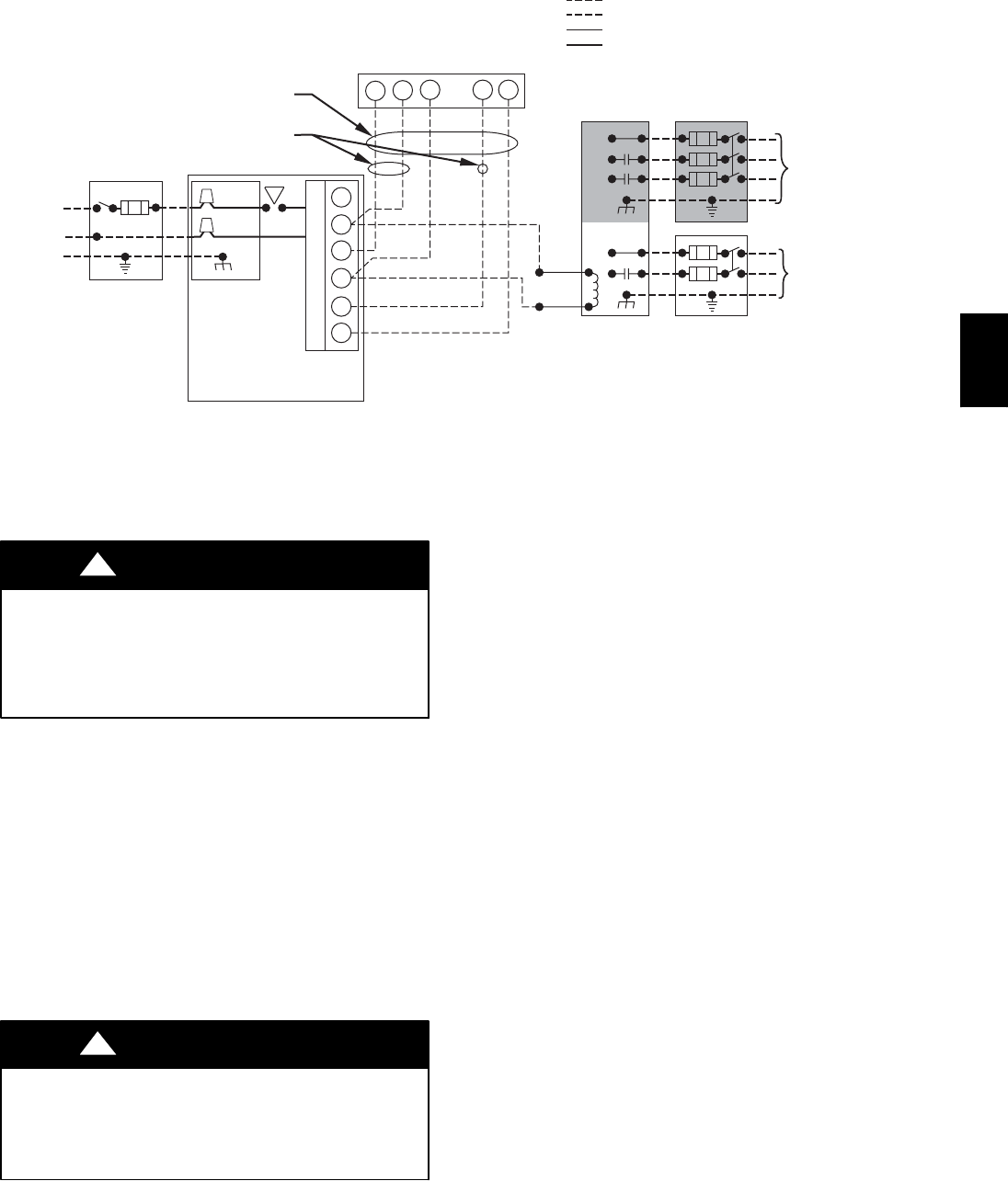
115-VOLT FIELD-
SUPPLIED
FUSED
DISCONNECT
JUNCTION
BOX
CONTROL
BOX
24-VOLT
TERMINAL
BLOCK
THREE-WIRE
HEATING-
ONLY
FIVE
WIRE
NOTE 2
NOTE 1
1-STAGE
THERMOSTAT
TERMINALS
FIELD-SUPPLIED
FUSED DISCONNECT
CONDENSING
UNIT
FURNACE
COM
R
WCY RG
GND
GND
FIELD 24-VOLT WIRING
FIELD 115-, 208/230-, 460-VOLT WIRING
FACTORY 24-VOLT WIRING
FACTORY 115-VOLT WIRING
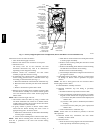
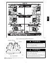
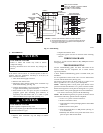
Connect Y/Y2-terminal as shown for proper operation.
Some thermostats require a "C" terminal connection as shown.
If any of the original wire, as supplied, must be replaced, use
same type or equivalent wire.
208/230- OR
460-VOLT
THREE
PHASE
208/230-
VOLT
SINGLE
PHASE
WHT
BLK
WHT
BLK
A95236
W/W1
W2
Y/Y2
G
NOTES: 1.
2.
3.
A95236
Fig. 15 -- Field Wiring
J. WINTERIZING
UNIT DAMAGE HAZARD
Failure to follow this caution may result in furnace
component damage.
Freezing condensate left in the furnace may damage the
furnace.
CAUTION
!
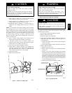
If the furnace will be off for an extended period of time in a
structure where the temperature will drop to 32_F(0_C) or
below, winterize a s follows:
1. Turn off electrical supply to furnace.
2. Remove main furnace door.
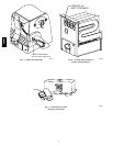
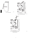
3. Disconnect upper inducer housing drain connection cap
from inducer housing. (See Fig. 18.)
4. Connect field-- supplied 1/2--in. I.D. inducer housing tube
to upper inducer housing drain connection.
5. Insert funnel in tube and pour one quart of antifreeze,
propylene glycol (RV, swimming pool antifreeze, or
equivalent) into funnel/tube until it is visible at point
where condensate enters open drain. (See Fig. 19.)
UNIT DAMAGE HAZARD
Failure of plastic components may occur.
Do not use ethylene glycol (Prestone II antifreeze/coolant or
equivalent automotive type).
CAUTION
!
6. Replace drain connection cap and clamp to inducer
housing.
7. Replace main furnace door.
8. Propylene glycol need not be removed before restarting
furnace.
WIRING DIAGRAMS
See Fig. 15, 16 and 21 for the Deluxe 4-- Way Multipoise Furnace
wiring diagrams.
TROUBLESHOOTING
Use the troubleshooting guide, the status code LED on the
furnace control and the component test to isolate furnace
operation problems.
A more detailed troubleshooting guide is available from your
distributor.
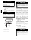
For an explanation of status codes, refer to service label located
on back of main furnace door (See Fig. 20.)
The furnace control stores all status codes for a period of 72
hours, regardless of 115-- v or 24--v power interruption.
NOTE: Removing blower access panel opens blower access
panel door switch and terminates 115-- v power to furnace control.
Before removing blower access panel or turning of f 115--v power,
look into blower access panel sight glass for current LED status.
1. To retrieve status code, proceed with the f ollowing:
NOTE: NO thermostat signal may be present at furnace control
and all blower time delay periods must be completed.
a. Leave 115--v power to furnace turned on.
b. Remove main furnace door.
c. Lookintobloweraccesspanelsight glassfor currentLED
status code.
d. Remove blower access panel.
e. Turn setup switch SW1 --1 to ON position. (See Fig. 16
or 21 for location.)
f. Manually close blower access panel door switch. Use a
piece of tape to hold switch closed.
58MVC