


12
ELECTRICAL SHOCK, UNIT MAY NOT OPERATE
HAZARD
Failure to follow this warning could result in personal
injury or death.
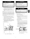
Blower access panel door switch opens 115--v power to
furnace control. No component operation can occur unless
switch is closed. Caution m ust be taken when ma nually
closing this switch for service purposes.
!
WARNING
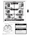
g. TheAMBER LEDwillflashthe statuscodes in theorder
of occurence. Record status codes until status code 11
flashes (1 short and 1 long).
h. After status code #11 flashes, the status codes willrepeat
until setup switch SW1--1 i s turned off.
i. Remove tape to release blower access panel door switch
and replace blower access panel.
j. Operate furnace through 1 heat cycle to test for proper
operation and check LED status.
k. Iffurnaceisoperating properlyandLEDsindicateproper
operation, replace main furnace door.
2. Status codes are erased after 72 hours or they can be
manually erased by performing the following procedure:
a. Lookintobloweraccesspanelsight glassfor currentLED
status code.
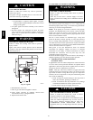
b. Remove blower access panel.
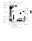
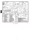
c. Turn setup switch SW1 --1 to ON position. (See Fig. 16
or 21 for location.)
d. Jumper thermostat terminals R, W/W1, and Y/Y2 on
furnace control.
e. Manually close blower access panel door switch. Use a
piece of tape to hold switch closed.
f. After status code 11 flashes for at least 2 times, remove
R, W/W1, and Y/Y2 jump ers.
g.TurnsetupswitchSW1--1toOFFposition.
h. Remove tape to release blower access panel door switch
and replace blower access panel.
i. Operate furnace through 1 heat cycle to check for proper
operation and check LED status.
j. IffurnaceisoperatingproperlyandLEDsindicateproper
operation, replace main furnace door.
3. The control can also assist in troubleshooting by
performing a Component Test. The Component Test will
functionally operate all furnace components, except the
gas valve.
NOTE: The component test feature will not operate if the
furnace control is receiving any thermostat signals or until all
time delays have expired.
a. To initiate Component Test proceed w ith the following:
(1.) Leave 115--v power to furnace turned on.
(2.) Remove main furnace door.
(3.) Remove blower access panel.
(4.)TurnsetupswitchSW1--6toONposition.
(5.) Manually close blower access panel door switch.
Use a piece of tap e to hold switch c losed.
b. When items (1) through (5) above have been completed,
the following will occur:
(1.) Inducer motor operates at medium speed through
step (3), then turns o ff.
(2.) After w aiting f or 15 sec, hot surface igniter i s
energized for 15 s ec, then de--energized.
(3.) Main blowermotoroperatesatmidrangeairflowfor
15 sec, then turns off.
(4.) After component operation test is completed, 1 or
more fault codes (11, 25, 41, or 42) will flash. See
service label on back of main furnace door or Fig.
20 for explanation of codes.
NOTE: To repeat component test, turn setup switch SW1-- 6 to
OFF and then back to ON.
c. After component test, perform the following:
(1.) Remove tape to release blower access panel door
switch and turn setup switch SW1--6 to OFF
position.
(2.) Replace blower access panel.
(3.) Operate furnace through 1 heat cycle to check for
proper operation and check LED status.
(4.) If furnace is operating properly and LEDs indicate
proper operation, replace main furnace door.
58MVC