


19
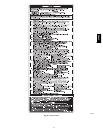
25 INVALID MODEL SELECTION OR
SETUP ERROR – If status code 25 only
ashes 4 times on power-up the control is
missing its model plug PL4 and is
defaulting to the model selection stored in
memory. If status code 25 ashes
continuously it could indicate any of the
following:
- Model plug PL4 is missing and there is
no valid model stored in permanent
memory. This will happen if you forget
to install the model plug PL4 on a
service replacement control.
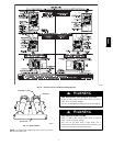
- Thermostat call with SW1-1 ON.
- Thermostat call with SW1-6 ON.
- SW1-1 and SW1-6 both ON.
- Two dierent furnace models twinned.
- Service replacement control does not
recognize new model plugs HK70EZ017
thru HK70EZ021. Need board software
version V12 or later.
31 MEDIUM-HEAT PRESSURE SWITCH OR
HPSR RELAY DID NOT CLOSE OR
REOPENED - Check for:
- HPSR relay may be defective.
- See status code 32.
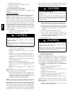
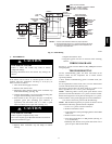
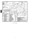
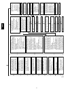
41 BLOWER MOTOR FAULT – Indicates the
blower failed to reach 250 RPM or the
blower failed to communicate within the
prescribed time limits. Thirty seconds
after being turned ON or ten seconds
during steady-state operation. Turn power
o and check the following items rst
before proceeding to the next step.
- Rubbing blower wheel.
- Loose blower wheel.
- Wiring from furnace control to blower
motor.
Remove the R thermostat connection from
the furnace control, disconnect both
connectors from the blower motor PL13
and PL14. Does the blower wheel turn
freely?
Replace the blower control module attached to
the blower motor. Follow the instructions with
the blower control module to make sure the
entire blower motor does not need to be
replaced.
Turn power back on. Is there 115VAC at
PL14-5 and PL14-4?
You have an open wire or bad
terminal on either the BLACK or
WHITE power leads between
the furnace control and the
blower motor. If you have a
power choke disconnect it and
check continuity.
YES
YES
NO
NO
Is there 12-VDC at PL13-1 RED (+) and
PL13-4 GREEN (-)?
YES
NO
Is there 12-VDC at PL3-1 RED (+) and
PL3-2 GREEN (-)?
Replace the furnace control.
NO
You have an open wire or bad
terminal on either the RED or
GREEN wire between the
furnace control and the blower
motor.
YES
Is there 5-VDC at PL13-2 YELLOW (+)
and PL13-4 GREEN (-)?
Is there 5-VDC at PL3-3
YELLOW (+) and PL3-2
GREEN (-)?
NO
NO
You have an open wire or bad
terminal on the YELLOW wire
between the furnace control and
the blower motor.
YES
YES
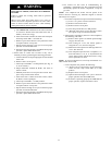
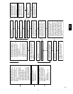
The voltage just measured should be
very stable and should not uctuate more
than .02-VDC. If the voltage uctuates
more than this get a dierent voltmeter
before proceeding.
Turn power o, disconnect PL13 and
PL14 from the blower motor, then turn
power back on. Connect a DC voltmeter
across PL13-3 BLUE (+) and PL13-4
GREEN (-). The voltage should be near
0-VDC but it will uctuate briey several
times a second. If you have an analog
voltmeter the needle will briey go high
several times a second. If you have a
digital voltmeter with a bar graph it will
show a large change in magnitude on the
bar graph several times a second. If you
have a standard digital voltmeter it will
show a brief uctuation in voltage and the
magnitude may vary depending on the
voltmeter used.
Does the voltage uctuate as described in the
previous step?
Connect a DC voltmeter across PL3-4 BLUE
(+) and PL3-2 GREEN (-). Does the voltage
uctuate as described two steps back?
You have an open wire or bad terminal on the
BLUE wire between the furnace control and the
blower motor.
NO
Replace the furnace control.
YES
Turn power o, reconnect PL13 and
PL14 to the blower motor, then turn
power back on. Connect a DC voltmeter
across PL3-3 YELLOW (+) and PL3-2
GREEN (-). Does the voltage uctuate
more than it did in the previous step?
NO
YES
YES
NO
Replace the blower control module attached to
the blower motor. Follow the instructions with
the blower control module to make sure the
entire blower motor does not need to be
replaced.
42 INDUCER MOTOR FAULT – Indicates the
inducer motor has not started within 20
seconds after a call for heat, the inducer
motor RPM is outside its valid range of
operation, or the inducer RPM signal was
lost for 5 seconds during operation.
Check for:
- Proper vent sizing.
- Failed inducer motor.
- Restricted combustion air supply.
- Improper motor wiring.
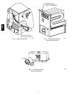
A07583
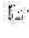
58MVC