


39
NOTE: Using the 2 cu. ft. or 5 cu. ft. gas meter dial provides
greater accuracy in verifying gas input rate.
If clocked rate does not match required input from Step 1,
increase manifold pressure to increase input or decrease manifold
pressure to decrease input. Repeat steps b through e until correct
high heat input is achieved. Re--install high--heat regulator seal
cap on gas valve.
8. Set high heat temperature rise.
Jumper R to W/W1 and W2 to check high--gas--heat tem-
perature rise. Do not exceed temperature rise ranges spe-
cified on furnace rating plate for high heat. The furnace
must operate within the temperature rise ranges specified
on the furnace rating plate.
Determine the air temperature rise as follows:
NOTE: Blower access door must be installed when taking
temperature rise reading. Leaving blower access door off will
result in incorrect temperature measurements.
a. Verify the furnace is operating in high heat per Step 6.
Place thermometers in return and supply ducts as close
to furnace as possible. Be sure thermometers do not see
radiant heat from heat exchangers. Radiant heat affects
temperature rise readings.This practice is particularly im-
portant with straight--run ducts.
b. When thermometer readings stabilize, subtract return--air
temperaturefromsupply--airtemperatureto determineair
temperature rise.
NOTE: If the temperature rise is outside this range, first check:
(1.) Gas input for low--and high--heat operation.
(2.) Derate for altitude if applicable.
(3.) Return and supply ducts for excessive restrictions
causing static pressures greater than 0.50--in. wc.
(4.) Dirty filter.
c. Adjust air temperature rise by adjusting blower speed. In-
crease blower speed to reduce temperature rise. Decrease
blower speed to increase temperature rise. For high heat,
speed selection can be med--high, med (5--speed blowers
only), or med--low (factory setting).
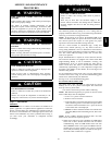
ELECTRICAL SHOCK HAZARD
Failure to follow this warning could result in personal
injury or death.
Disconnect 115--v electrical power before changing speed
tap.
!
WARNING
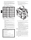
d. To change motor speed selection for high heat, remove
blowermotorleadfrom controlHI--HEAT terminal.(See
Fig. 33.) Select desired blower motor speed lead from 1
of the other terminals and relocate it to the HI--HEAT ter-
minal. DO NOT use the low--heattap thatwas already set.
(See Table 13 for lead color identification). Reconnect
original lead to SPARE terminal.
e. Repeat steps a thru e.
f. When correct high heat input rate and temperature riseis
achieved, turn gas valve ON/OFF switch to OFF.
g. Release Blower Access Door switch.
h. Remove manometer or similar device from gas valve.
i. Re--install manifold pressure tap plug in gas valve. (See
Fig 54.)
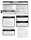
FIRE HAZARD
Failure to reinstall manifold pressure tap plug in gas valve
could result in personal injury, property damage or death.
Reinstall manifold pressure tap plug in gas valve to prevent
gas leak.
!
WARNING
j. Remove thermostat jumper wire from furnace control
board.
k. Turn LHT switch OFF.
l. Turn gas valve ON/OFF switch to ON.
m. Proceed to Step 9, “Set Blower Off Delay” before in-
stalling blower access door.
FURNACE OVERHEATING HAZARD
Failure to follow this caution may result in reduced furnace
life.
Recheck temperature rise. It must be within limits specified
on the rating plate. Recommended operation is at the
midpoint of rise range or slightly above.
CAUTION
!
9. Set Blower Off Delay
a. Remove Blower Access Door if installed.
b. Turn Dip switch 2 and 3 ON or OFF for desired blower
off delay. (See Table 14 and Fig 34.)
10. Set thermostat heat anticipator.
a. Mechanical thermostat -- Set thermostat heat anticipator
to match the amp. draw of the electrical components in
the R--W/W1 circuit. Accurate amp. draw readings can
beobtainedatthewiresnormallyconnected tothermostat
subbase terminals, R and W. The thermostat anticipator
should NOT be in the circuit while measuring current.
(1.) Set LHT switch on furnace control board to ON.
(2.) Remove thermostat from sub--base or from wall.
(3.) Connect an amp. meter as shown in Fig. 55 across
the R and W subbase terminals or R and W wires at
wall.
(4.) Record amp. draw across terminals when furnace is
in low heat and after blower starts.
(5.) Set heat anticipatoron thermostat perthermostat in-
structions and install on subbase or wall.
(6.) Turn LHT switch OFF.
(7.) Install blower access door.
b. Electronic thermostat: Set cycle rate for 3 cycles per hr.
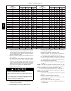
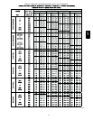
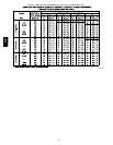
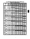
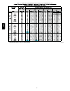
11. Set airflow CFM for cooling
Select the desired blower motor speed lead for cooling air-
flow. See Table 5--Air Delivery--CFM (With Filter). See
Table 13 for lead color identification.
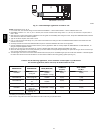
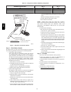
Table 13 – Speed Selection
COLOR SPEED AS SHIPPED
White Common BLW
Black High COOL
Yellow Me d --- H igh SPARE
Orange† Med SPARE
Blue Med --- Lo w HI---HEAT
Red Low* LO HEAT
* Continuous---blower speed---as shipped default
{ Not all models equipped with 5 speed motors
58CT