


22
6. Reinstall cover to J--Box. Do not pinch wires between
cover and bracket.
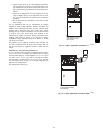
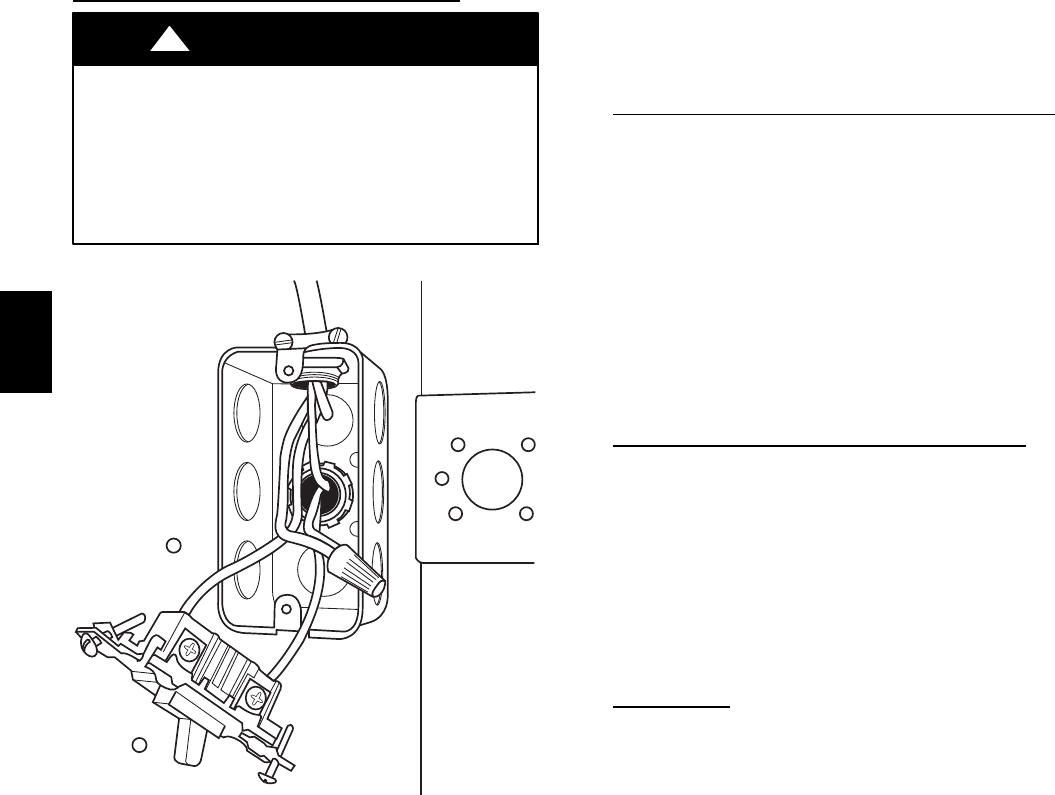
Electrical Box on Furnace Casing Side. See Fig.
25.
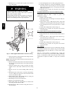
FIRE OR ELECTRICAL SHOCK HAZARD
Failure to follow this warning could result in personal
injury, death, or property damage.
If field--supplied manual disconnect switch is to be mounted
on furnace casing side, select a location where a drill or
fastener cannot damage electrical or gas components.
!
WARNING
A03221
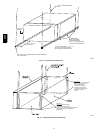
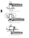
Fig. 25 -- Field-- Supplied Electrical Box on Furnace Casing
1. Select and remove a hole knockout in the casing where the
electrical box is to be installed.
NOTE: Check that duct on side of furnace will not interfere with
installed electrical box.
2. Remove the desired electrical box hole knockout and posi-
tion the hole in the electrical box over the hole in the fur-
nace casing.
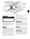
3. Fasten the electrical box to casing by driving two field--
supplied screws from inside electrical box into casing
steel.
4. Remove and save two screws holding J--Box. (See Fig.
24.)
5. Pull furnace power wires out of 1/2--inch (12 mm) diamet-
er hole in J--Box. Do not loosen wires from strain--relief
wire--tie on outside of J--Box.
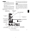
6. Route furnace power wires through holes in casing and
electrical box and into electrical box.
7. Pull field power wires into electrical box.
8. Remove cover from furnace J--Box.
9. Route field ground wire through holes in electrical box
and casing, and into furnace J--Box.
10. Reattach furnace J--Box to furnace casing with screws re-
movedinStep4.
11. Secure field ground wire to J--Box green ground screw.
12. Complete electrical box wiring and installation. Connect
line voltage leads as shown in Fig. 23. Use best practices
(NEC in U.S. and CSA C22.1 in Canada) for wire bush-
ings, strain relief, etc.
13. Reinstall cover to J--Box. Do not pinch wires between
cover and bracket.
POWER CORD INSTALLATION IN FURNACE
J--BOX
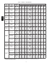
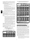
NOTE: Power cords must be able to handle the electrical
requirements listed in Table 7. Refer to power cord
manufacturer’s listings.
1. Remove cover from J--Box.
2. Route listed power cord through 7/8--inch (22 mm) dia-
meter hole in J--Box.
3. Secure power cord to J--Box bracket with a strain relief
bushing or a connector approved for the type of cord used.
4. Secure field ground wire to green ground screw on J--Box
bracket.
5. Connect line voltage leads as shown in Fig. 23.
6. Reinstall cover to J--Box. Do not pinch wires between
cover and bracket.
BX. CABLE INSTALLATION IN FURNACE
J--BOX
1. Remove cover from J--Box.
2. Route BX cable into 7/8--inch (22 mm) diameter hole in
J--Box.
3. Secure BX cable to J--Box bracket with connectors ap-
proved for the type of cable used.
4. Secure field ground wire to green ground screw on J--Box
bracket.
5. Connect line voltage leads as shown in Fig. 23.
6. Reinstall cover to J--Box. Do not pinch wires between
cover and bracket.
24-- V
WIRING
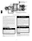
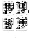
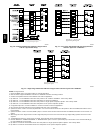
Make field 24--v connections at the 24--v terminal strip. (See Fig.
33.) Connect terminal Y/Y2 as shown in Fig. 26--32 for proper
cooling operation. Use only AWG No. 18, color--coded, copper
thermostat wire.
The 24--v circuit contains an automotive--type, 3--amp. fuse
located on the control. Any direct shorts during installation,
service, or maintenance could cause this fuse to blow. If fuse
replacement is required, use ONLY a 3--amp. fuse of identical
size.
58CT