


35
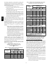
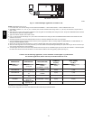
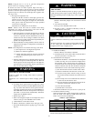
Table 10 – 2--Stage Furnace Setup Switch Description
SETUP
SWITCH NO.
SWITCH
NAME
NORMAL
POSITION
DESCRIPTION
OF USE
SW --- 1 Adaptive Heat Mode OFF
When OFF, allows 2---stage operation with a single stage thermostat.
Turn ON when using 2 stage thermostat to allow Low Heat opera---
tion when R to W/W1 closes and High Heat operation when R to
W/W1 and W2 close.
SW --- 2 Blower OFF delay ON or OFF
Control blower OFF delay time. Used in conjunction with SW---3.
See Table 14.
SW --- 3 Blower OFF delay ON or OFF
Control blower OFF delay time. Used in conjunction with SW---2.
See Table 14.
Step 2 — Start--Up Procedures
FIRE AND EXPLOSION HAZARD
Failure to follow this warning could cause personal injury,
death and/or property damage.
Never test for gas leaks with an open flame. Use a
commercially available soap solution made specifically for
the detection of leaks to check all connections.
!
WARNING
1. Purge gas lines after all connections have been made.
2. Check gas lines for leaks.
ELECTRICAL SHOCK HAZARD
Failure to follow this warning could result in personal
injury, or death.
Blower access door switch opens 115--v power to control.
No component operation can occur unless switch is closed.
Caution must be taken when manually closing this switch
for service purposes.
!
WARNING
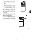
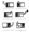
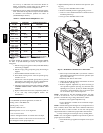
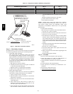
3. To Begin Component Self--Test:
Remove blower access door. Disconnect the thermostat R
lead from furnace control board. Manually close blower
door switch. Short (jumper) the COM--24v terminal on
control to the TEST/TWIN 3/16--in. (8 mm) quick--con-
nect terminal on control until the LED goes out (approx-
imately 2 sec). Gas valve and humidifier will not be turned
on. Remove jumper from terminals. (See Fig. 33 and
Table 10.)
NOTE: The furnace control allows all components, except the
gas valve, to be run for short period of time. This feature helps
diagnose a system problem in case of a component failure.
Component test feature will not operate if any thermostat signal is
present at the control.
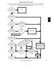
Refer to service label attached to furnace or See Fig. 56.
Component test sequence is as follows:
a. LED will display previous status code 4 times.
b. Inducer motor starts on high--speed and continues to run
until Step g of component test sequence.
c. Hot surface igniter is energized for 15 sec., then off.
d. Blower motor operates on LO--HEAT speed for 10 sec.
e. Blower motor operates on HI--HEAT speed for 10 sec.
f. Blower motor operates on COOL speed for 10 sec.
g. Inducermotor goesto low--speed for 10 sec., then stops.
h. Reconnect R lead to furnace control board, remove tape
from blower door switch and re--install blower door.
4. Operate furnace per instruction on inner door.
5. Verify furnace shut down by lowering thermostat setting
below room temperature.
6. Verify furnace restarts by raising thermostat setting above
room temperature.
Step 3 — A djustments
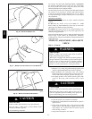
FIRE HAZARD
Failure to follow this warning could result in injury, death
and/or property damage.
DO NOT bottom out gas valve regulator adjusting screw.
This can result in unregulated manifold pressure and result
in excess over--fire and heat exchanger failures.
!
WARNING
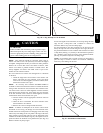
FURNACE DAMAGE HAZARD
Failure to follow this caution may result in reduced furnace
life.
DO NOT re--drill orifices. Improper drilling (burrs, out--of
round holes, etc.) can cause excessive burner noise and
misdirection of burner flames. This can result in flame
impingement of heat exchangers, causing failures. (See Fig.
49.)
CAUTION
!
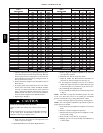
Furnace gas input rate on rating plate is for installations at
altitudes up to 2000 ft. (610 M). Furnace input rate must be
within +/--2% of furnace rating plate input. For altitudes above
5500 ft. (1676 M), a field--supplied high altitude pressure switch
is required.
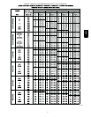
1. Determine the correct gas input rate.
In the U.S.:
The input rating for altitudes above 2,000 ft. (610 M) must
be reduced by 4% for each 1,000 ft. (305 M) above sea
level.
For installations below 2000 ft. (610 M), refer to the unit
rating plate.
For installations above 2000 ft. (610 M), multiply the in-
put on the rating plate by the derate multiplier in Table 11
for the correct input rate.
EXAMPLE:
88,000 BTUH INPUT FURNACE INSTALLED AT 4300 FT. (1310
M)
Derate Furnace Input Rate
Furnace Input Rate X Multiplier = at Installation
at Sea Level Factor Altitude
88,000 X 0.90 = 79,200
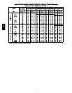
In Canada: The input rating must be reduced by 10% for
altitudes of 2,000 ft. (610 M) to 4,500 ft. (1372 M) above
58CT