


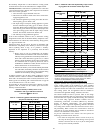
21
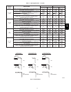
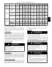
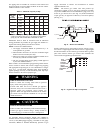
Table 7 – Electrical Data
V OLT S ---
H E RT Z ---
PHASE
OPERATING VOLTAGE
RANGE
MAX
UNIT
AMPS
FURNACE
SIZE
UNIT
AMPACITY#
MAXIMUM
WIRE
L EN GT H ---
FT. (M)‡
MAXIMUM
FUSE OR
CKT BKR
AMPS†
MINIMUM
WIRE
GAUGE
MAX* MIN.*
11 5 --- 6 0 --- 1 127 104 5.3 045---08/024045 7.42 49 (14.9) 15 14
11 5 --- 6 0 --- 1 127 104 7.1 045---12/036045 9.67 38 (11.5) 15 14
11 5 --- 6 0 --- 1 127 104 5.2 070---08/024070 7.22 51 (15.5) 15 14
11 5 --- 6 0 --- 1 127 104 7.3 070---12/036070 9.90 37 (11.2) 15 14
11 5 --- 6 0 --- 1 127 104 10.1 070---16/048070 13.42 27 (8.2) 15 14
11 5 --- 6 0 --- 1 127 104 8.2 090---14/042090 10.84 34 (10.3) 15 14
11 5 --- 6 0 --- 1 127 104 9.9 090---16/048090 13.0 28 (8.5) 15 14
11 5 --- 6 0 --- 1 127 104 12.9 090---20/060090 16.70 34 (10.3) 20 12
11 5 --- 6 0 --- 1 127 104 8.2 110---12/036110 10.76 34 (10.3) 15 14
11 5 --- 6 0 --- 1 127 104 10.1 110---16/048110 13.19 28 (8.5) 15 14
11 5 --- 6 0 --- 1 127 104 13.7 110---22/066110 17.60 32 (9.7) 20 12
11 5 --- 6 0 --- 1 127 104 10.2 135---16/048135 13.28 27 (8.2) 15 14
11 5 --- 6 0 --- 1 127 104 14.5 135---22/066135 18.61 30 (9.1) 20 12
11 5 --- 6 0 --- 1 127 104 15.0 155---20/060155 19.34 29 (8.8) 20 12
* Permissible limits of the voltage range at which the unit operates satisfactorily.
# Unit ampacity = 125% of lar gest operating componen t’s full load amps plus 100% of all other potential operating components (E AC, humidifier,
etc.) ful l l oad amps.
{ Time---delay type is recommended.
} Length shown is as measured 1 way along wire path between unit and service panel for maximum 2% voltage drop.
U.S. Installations: Make all electrical connections in accordance
with National Electrical Code (NEC) ANSI/NFPA 70--2008 and
any local codes or ordinances that might apply.
Canadian Installations: Make all electrical connections in
accordance with Canadian Electrical Code CSA C22.1 or
authorities having jurisdiction.
FIRE HAZARD
Failure to follow this warning could result in personal
injury, death, or property damage.
Do not connect aluminum wire between disconnect switch
and furnace. Use only copper wire.
!
WARNING
Use a separate branch electrical circuit with a properly sized fuse
or circuit breaker for this furnace. See Table 7 for wire size and
fuse specifications. A readily accessible means of electrical
disconnect must be located within sight of the furnace.
NOTE: Proper polarity must be maintained for 115--v wiring. If
polarity is incorrect, control LED status indicator light will flash
rapidly and furnace will NOT operate.
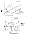
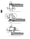
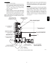
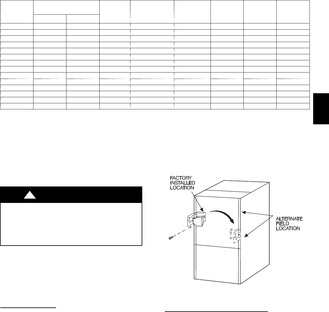
J --BOX RELOCA
TION
NOTE: If factory location of J--Box is acceptable, go to next
section (ELECTRICAL CONNECTION TO J--BOX).
NOTE: On 14” wide casing models, the J--Box shall not be
relocated to other side of furnace casing when the vent pipe is
routed within the casing.
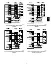
1. Remove and save two screws holding J--Box. (See Fig.
24.)
NOTE: The J--Box cover need not be removed from the J--Box
in order to move the J--Box. Do NOT remove green ground
screw inside J--Box. The ground screw is not threaded into the
casing flange and can be lifted out of the clearance hole in casing
while swinging the front edge of the J--box outboard of the
casing.
2. Cut wire tie on loop in furnace wires attached to J--Box.
3. Move J--Box to desired location.
4. Fasten J--Box to casing with the two screws removed in
Step 1.
5. Route J--Box wires within furnace away from sharp edges,
rotating parts, and hot surfaces.
TWO
A02099
Fig. 24 -- Relocating J--Box
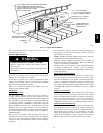
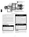
ELECTRICAL CONNECTION TO
J--BOX
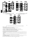
Field--Supplied Electrical Box on Furnace J--Box Bracket. See
Fig. 26.
1. Remove cover from furnace J--Box.
2. Attach electrical box to furnace J--Box bracket with at least
two field--supplied screws through holes in electrical box
into holes in bracket. Use blunt--nose screws that will not
pierce wire insulation.
3. Route furnace power wires through holes in electrical box
and J--Box bracket, and make field--wire connections in
electrical box. Use best practices (NEC in U.S. and CSA
C22.1 in Canada) for wire bushings, strain relief, etc.
4. Route and secure field ground wire to green ground screw
on J--Box bracket.
5. Connect line voltage leads as shown in Fig. 23.
58CT