


20
115-VOLT FIELD-
SUPPLIED
FUSED
DISCONNECT
JUNCTION
BOX
CONTROL
BOX
24-VOLT
TERMINAL
BLOCK
THREE-WIRE
HEATING-
ONLY
FIVE
WIRE
NOTE 2
NOTE 1
1-STAGE
THERMOSTAT
TERMINALS
FIELD-SUPPLIED
FUSED DISCONNECT
CONDENSING
UNIT
FURNACE
COM
R
WCY RG
GND
GND
FIELD 24-VOLT WIRING
FIELD 115-, 208/230-, 460-VOLT WIRING
FACTORY 24-VOLT WIRING
FACTORY 115-VOLT WIRING
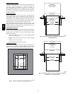
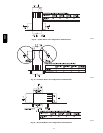
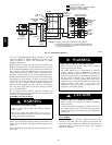
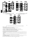
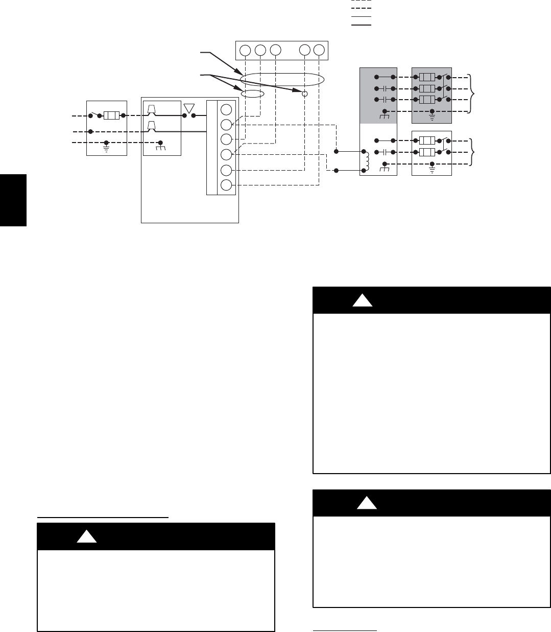
Connect Y/Y2-terminal as shown for proper operation.
Some thermostats require a "C" terminal connection as shown.
If any of the original wire, as supplied, must be replaced, use
same type or equivalent wire.
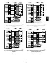
208/230- OR
460-VOLT
THREE
PHASE
208/230-
VOLT
SINGLE
PHASE
WHT
BLK
WHT
BLK
W/W1
W2
Y/Y2
G
NOTES: 1.
2.
3.
A95236
Fig. 23 -- Field Wiring Diagram
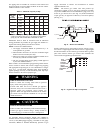
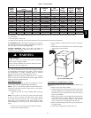
A 1/8--in. (3 mm) NPT plugged tapping, accessible for test gauge
connection, MUST be installed immediately upstream of gas
supply connection to furnace and downstream of manual
equipment shutoff valve.
Piping should be pressure and leak tested in accordance with
NFGC in the United States or CAN/CSA--B149.1--05 in Canada,
local, and national plumbing and gas codes before the furnace has
been connected. After all connections have been made, purge
lines and check for leakage at furnace prior to operating furnace.
If pressure exceeds 0.5 psig (14--in. wc), gas supply pipe must be
disconnected from furnace and capped before and during supply
pipe pressure test. If test pressure is equal to or less than 0.5 psig
(14--in. wc), turn off electric shutoff switch located on furnace gas
control valve and accessible manual equipment shutoff valve
before and during supply pipe pressure test. After all connections
have been made, purge lines and check for leakage at furnace
prior to operating furnace.
The gas supply pressure shall be within the maximum and
minimum inlet supply pressures marked on the rating plate with
the furnace burners ON and OFF.
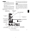
ELECTRICAL
CONNECTIONS
ELECTRICAL SHOCK HAZARD
Failure to follow this warning could result in personal
injury or death.
Blower access panel door switch opens 115--v power to
control. No component operation can occur. Do not bypass
or close switch with panel removed.
!
WARNING
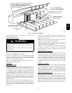
See Fig. 23 for field wiring diagram showing typical field 115--v
wiring. Check all factory and field electrical connections for
tightness.
Field--supplied wiring shall conform with the limitations of 63_F
(33_C) rise.
ELECTRICAL SHOCK AND FIRE HAZARD
Failure to follow this warning could result in personal
injury, death, or property damage.
The cabinet MUST have an uninterrupted or unbroken
ground according to NEC ANSI/NFPA 70--2008 and
Canadian Electrical Code CSA C22.1 or local codes to
minimize personal injury if an electrical fault should occur.
This may consist of electrical wire, conduit approved for
electrical ground or a listed, grounded power cord (where
permitted by local code) when installed in accordance with
existing electrical codes. Refer to the power cord
manufacturer’s ratings for proper wire gauge. Do not use
gas piping as an electrical ground.
!
WARNING
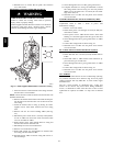
FURNACE MAY NOT OPERATE HAZARD
Failure to follow this caution may result in intermittent
furnace operation.
Furnace control must be grounded for proper operation or
else control will lock out. Control must remain grounded
through green/yellow wire routed to gas valve and manifold
bracket screw.
CAUTION
!
115--V WIRING
Verify that the voltage, frequency, and phase correspond to that
specified on unit rating plate. Also, check to be sure that service
provided by utility is sufficient to handle load imposed by this
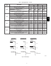
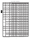
equipment. Refer to rating plate or Table 7 for equipment
electrical specifications.
58CT